
Microprocessor

A microprocessor and processor core technology, applied in the direction of electrical digital data processing, instrumentation, error detection/correction, etc., to achieve the effect of convenient access

Inactive Publication Date: 2004-10-27
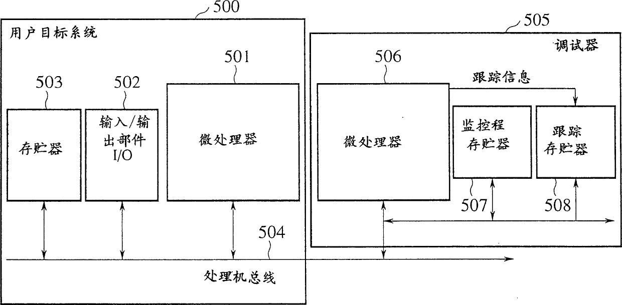
KK TOSHIBA +1
View PDF1 Cites 1 Cited by
  • Summary
  • Abstract
  • Description
  • Claims
  • Application Information

AI Technical Summary

Problems solved by technology

Although the prior art of FIG. 1 may have a trigger function in the debug microprocessor 506, there will also be an additional signal for providing trigger information

Method used


Image

  • Microprocessor
  • Microprocessor
  • Microprocessor

Examples


example 2

[0457] (Example 2): Program counter trace of indirect jump instruction.

[0458] Figure 31 is an example of program counter trace signals for an indirect jump instruction.

[0459] As a response to the first indirect jump instruction "jr1", the signal PCST[2:0] indicates that the state is JMP, and the signal TPC starts to transmit the target program counter signal. As a response to the non-entry branch instruction "bne", the signal PCST[2:0] indicates that the state is SEQ, and as a response to the second indirect branch instruction "jr2", the signal TPC stops transmitting the first indirect jump instruction " The target program counter signal of jr1" begins to transmit the target program counter signal for the second instruction "jr2". At this time, the signal PCST[2:0] indicates that the state is JMP.

[0460] (Example 3) Program counter trace for exception and indirect jump instructions.

[0461] Figure 32 is an example of a program counter trace for exception and indire...


PUM


Abstract

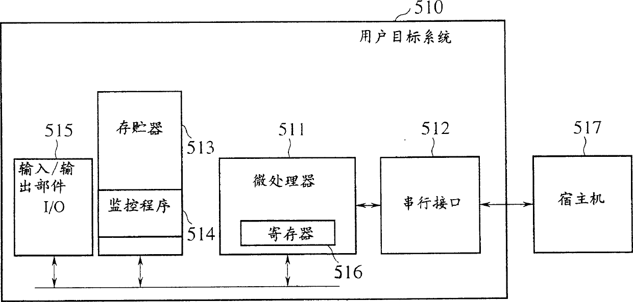
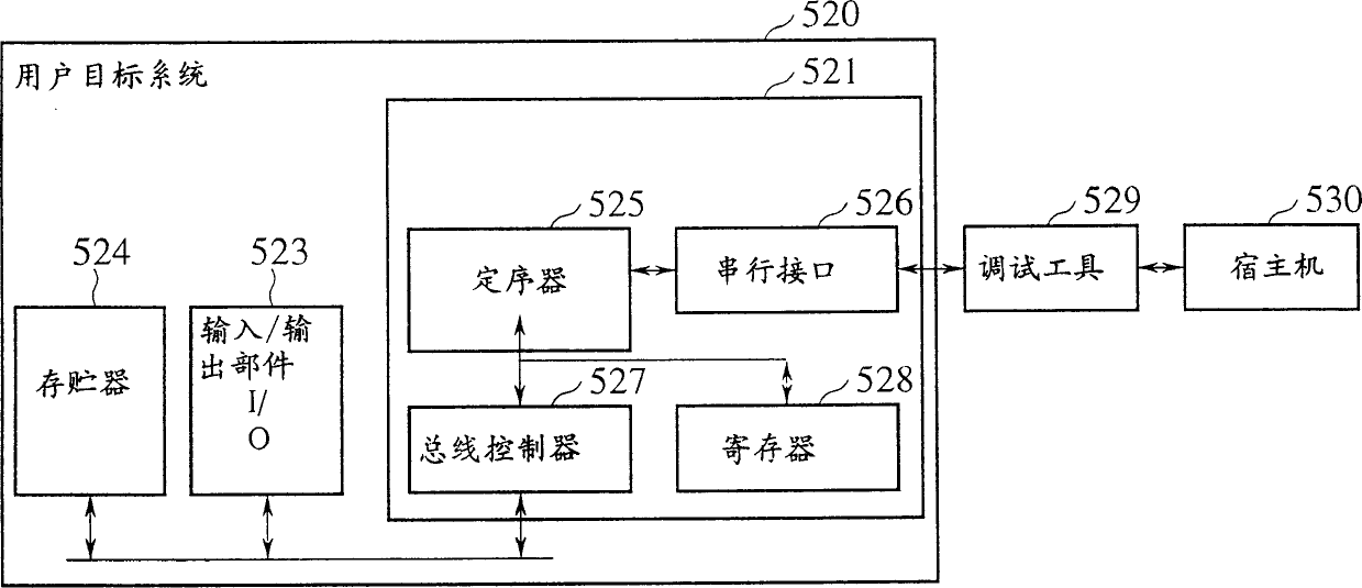
A microprocessor (10) has a processor core (20) and a debug module (30). The processor core (20) executes a user program and a monitor program for debugging a user target system (70). The debug module (30) serves as an interface with a debug tool (60), to let the processor core (20) execute the monitor program stored in the debug tool (60). The debug module (30) makes an interrupt or exception request to switch the processor core (20) from the user program to the monitor program.

Description

[0001] This case is a divisional application of the patent application whose Chinese patent application number is 01144011.2. Technical field: [0002] The invention relates to a microprocessor and a debugging system. The debug system is used to trace the function of the program counter and notify the user that the current address or data has been accessed. Background technique: [0003] Fig. 1 is a debugging system realized according to the prior art, which is called an internal circuit emulator. [0004] The system includes: user target system 500 and a debugger 505 for debugging the target system 500, the target system 500 contains a microprocessor 501, a memory 503 and an input and output unit 502, and the debugger contains a debugging microprocessor 506 and a monitoring program storage 507 . [0005] To debug the target system 500, the microprocessor 501 is removed or disabled, and the pin of the debugger 505 is connected to the microprocessor 501, so that the micropr...

Claims


Application Information

Patent Timeline
Patent Type & Authority Applications(China)
IPC IPC(8): G06F11/36
CPCG06F11/364G06F11/3656G06F11/22
Inventor 宫森高矢野达男
Owner KK TOSHIBA
Learn More