Sensor assembly for automatic dryer

A sensor component and sensor technology, which is applied in the field of dryers, can solve the problems of drying time period, heater and blower motor working beyond the required time, drying performance cannot be guaranteed, energy waste, etc.

Inactive Publication Date: 2004-11-03
LG ELECTRONICS INC
View PDF0 Cites 8 Cited by
  • Summary
  • Abstract
  • Description
  • Claims
  • Application Information

AI Technical Summary

Problems solved by technology

[0009] Optimum drying performance cannot always be guaranteed, causing the dryer unit to run longer, requiring more drying time cycles and causing the heater and blower motors to run longer than necessary, resulting in waste of energy

Method used


Image

  • Sensor assembly for automatic dryer
  • Sensor assembly for automatic dryer
  • Sensor assembly for automatic dryer

Examples


Embodiment Construction

[0039] Reference will now be made in detail to the preferred embodiments of the present invention, examples of which are illustrated in the accompanying drawings. Wherever possible, the same reference numbers will be used throughout the drawings to designate the same or like parts.

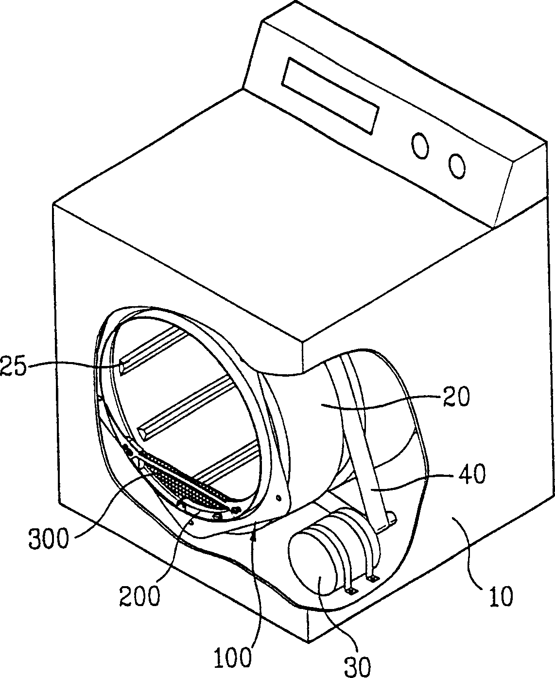
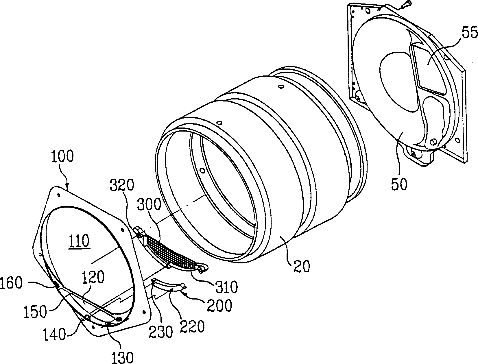
[0040] figure 1 is a partially cutaway perspective view showing the interior of a dryer according to a preferred embodiment of the present invention, figure 2 It is an exploded perspective view showing the combination of some parts of the dryer according to the preferred embodiment of the present invention.

[0041]refer to figure 1 with figure 2 , the drum 20 is rotatably mounted on figure 1 Shown in the cabinet 10 of the dryer. To this end, a belt 40 connects the motor 30 with the drum 20 installed inside the cabinet 10 . According to this system, since the belt 40 transmits power from the motor 30 to the drum 20 , the drum 20 can rotate inside the cabinet 10 .

[0042] The drum 20 has ...


PUM


Abstract

A sensor assembly is provided for an automatic drying machine having a rotatable drum containing a load of wet clothes to be dried wherein at least one sensing element is disposed on a surface of an elongated sensor body and is exposed to inside of the drum so as to make contact with the wet clothes. The sensor body is secured directly to a bulkhead having an air outlet opening and is provided at the air outlet opening for effective engagement with the wet clothes.

Description

[0001] Cross References to Related Applications [0002] This application claims priority from Korean Patent Application No. P2003-0026744 filed on Apr. 28, 2003, which is hereby incorporated by reference. technical field [0003] The present invention relates to dryers, and more particularly, to a sensor assembly for determining the dryness of wet laundry dried in an automatic dryer. Background technique [0004] The automatic dryer automatically dries the wet clothes (for example, clothes, etc.) after washing. Generally, dryers have a system for supplying hot air heated by a heater into a drying drum, and they are classified into exhaust type dryers and condensation type dryers. [0005] The exhaust type dryer dries the dry goods by exhausting the low-temperature and humid air that has been dried to the outside, sucking in fresh air, heating the air, and supplying the heated air to the drum. [0006] The condensing dryer dries the dried items by condensing the low-temper...

Claims


Application Information

Patent Timeline
Patent Type & Authority Applications(China)
IPC IPC(8): D06F58/02D06F58/28
CPCD06F2058/2838D06F58/28D06F34/18D06F58/38D06F2103/08D06F2103/10D06F2103/12
Inventor 朴秀原
Owner LG ELECTRONICS INC
Why Eureka
Try Eureka