Light amount control apparatus photographing apparatus, and filter

A light quantity adjustment and shooting device technology, applied in optical filters, instruments, optics, etc., can solve the problems of undisclosed ND filter light quantity adjustment, control mode switching without detailed description, inappropriate, etc.

Inactive Publication Date: 2004-11-03
CANON KK
View PDF9 Cites 27 Cited by
  • Summary
  • Abstract
  • Description
  • Claims
  • Application Information

AI Technical Summary

Problems solved by technology

[0020] In the prior art disclosed in Japanese Patent Application Laid-Open No. 8-43878, since the ND filter enters the opening in the open state of the diaphragm, light loss occurs when the diaphragm is opened.
In addition, because the concentration distribution of the ND filter is different in the vertical direction and the left-right direction in the diaphragm opening, when shooting a subject with a large distance difference, the blurred image is unnatural, especially when high-quality images are required. Still image shooting is not suitable for construction
[0021] In the prior art disclosed in JP-A No. 2002-64745 and JP-A-2002-204390, techniques for performing optimum diaphragm control in moving image shooting and still image shooting are disclosed, but Light quantity adjustment using an ND filter is not disclosed, and the prevention of diffraction by a small aperture is insufficient
[0022] In the prior art disclosed in Japanese Unexamined Patent Publication No. 2000-106649, although there is a degree of freedom in the control of the transmittance based on the aperture diameter of the diaphragm and the ND filter, there is no control for moving image shooting and still image shooting. Morphological switching is not specified

Method used


Image

  • Light amount control apparatus photographing apparatus, and filter
  • Light amount control apparatus photographing apparatus, and filter
  • Light amount control apparatus photographing apparatus, and filter

Examples


Embodiment approach 1

[0065] 1 to 11A to C are diagrams related to Embodiment 1. FIG.

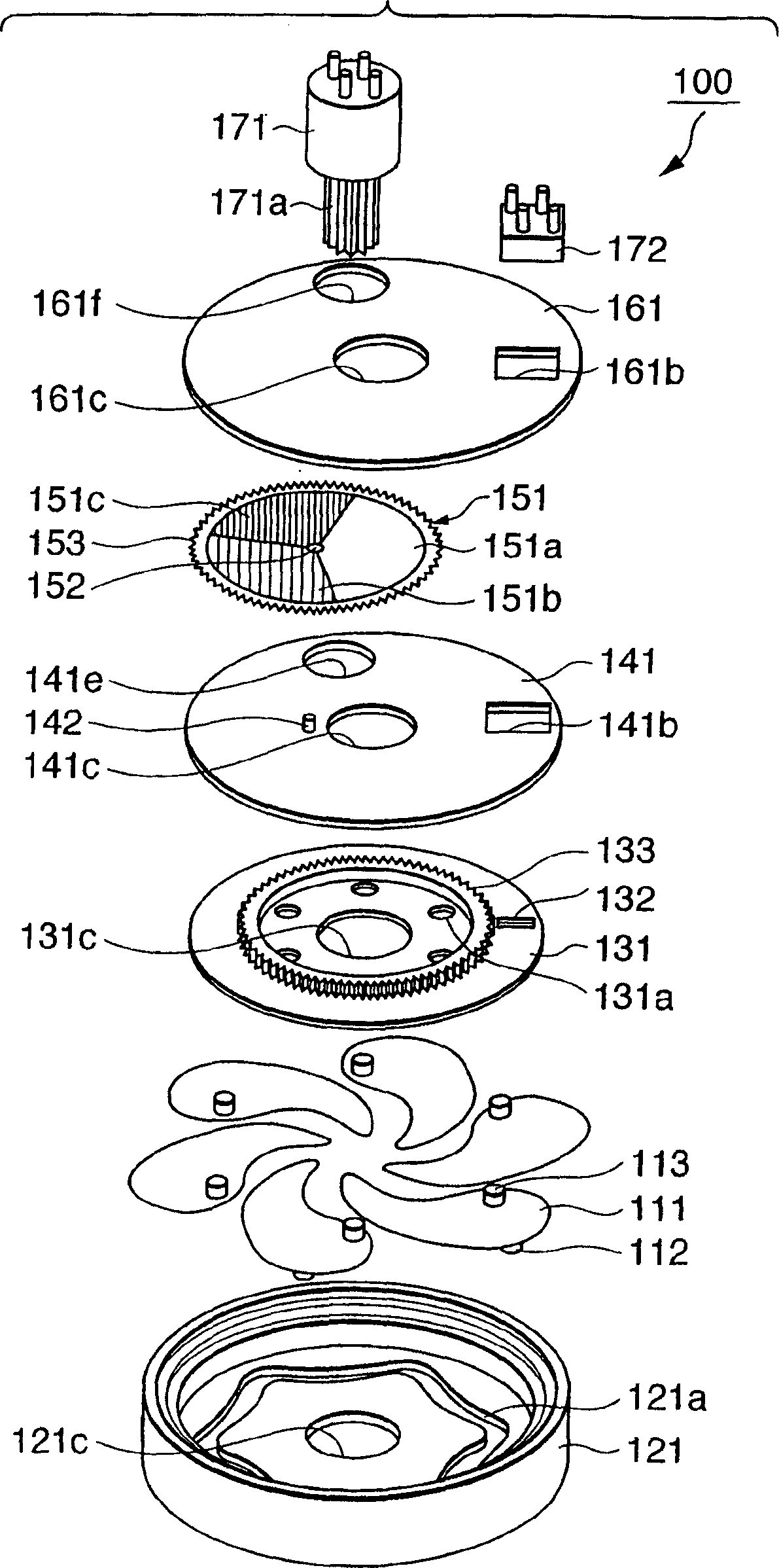
[0066] FIG. 1 is a perspective view of a main part of a light quantity adjusting device 100 in this embodiment. In the same figure, reference numeral 111 denotes a diaphragm blade having light-shielding properties over the entire area, and pins 112 and 113 for driving are embedded in the lower and upper surfaces of the diaphragm blades. Six diaphragm blades 111 of the same shape are used to form diaphragm openings. Furthermore, the larger the number of diaphragm blades 111, the closer the aperture shape becomes to a circle when the aperture is narrowed down, the naturalness of blurred images and the development at the top of the polygonal aperture are alleviated, but the manufacturing cost also increases. Therefore, in the aperture mechanism of the present embodiment, it is preferable to set the number of aperture blades between five and nine. In the present embodiment, six diaphragm blades are used as shown i...

Embodiment approach 2

[0172] The light quantity adjusting device used in Embodiment 1 is a device that drives the aperture blade and the ND filter with one actuator, while Embodiment 2 shown below shows that the aperture blade and the ND filter are driven by separate actuators. Morphology of the ND filter.

[0173] FIG. 12 is an exploded perspective view of a main part for explaining the structure of the light quantity adjusting device 200 according to the second embodiment, and corresponds to FIG. 1 of the first embodiment.

[0174] In the same figure, reference numeral 211 is a diaphragm blade having light-shielding properties over the entire area, and pins 212 and 213 for driving are embedded in the upper and lower surfaces thereof. The aperture blade 211 uses six blades of the same shape to form aperture openings.

[0175] Reference numeral 221 denotes a floor for holding the diaphragm blades 211, and an opening 221c that defines the maximum diameter of the light beam when the diaphragm is ope...

Embodiment approach 3

[0201] In the ND filter used in the above-described second embodiment, the disc-shaped filter is divided into a plurality of regions to give different optical densities, and the optical density distribution in each of the divided regions is uniform. The ND filter of the third embodiment shown below shows an embodiment in which the optical density changes in multiple steps or continuously along the circumferential direction of the disc-shaped filter.

[0202] 17A is a plan view for explaining the details of the optical density distribution of the ND filter 351 of the third embodiment, and corresponds to FIG. 13 of the second embodiment. 351 is a disk-shaped ND filter, and its mechanical configuration is the same as that of the first embodiment. The ND filter 151 and the ND filter 251 of Embodiment 2 are the same. That is, the ND filter 351 is formed on a transparent resin film with a thickness of 0.1 mm, such as a PET (polyethylene terephthalate) film, and the ND pattern descri...


PUM


Abstract

It is an object of this invention to independently control the F-number and the number of light attenuation steps of a multi-density ND filter by using a light amount control apparatus using an iris stop and the ND filter. The iris stop mechanism made up of a plurality of aperture blades and the ND filter having a multi-density pattern are stacked in a single unit. This simultaneously realizes continuous control of the F-number, multi-step control of the light attenuation ratio of the ND filter, a substantially circular stop aperture, and a uniform transmittance distribution in the stop aperture. In the first embodiment, the driving region of an actuator is divided into an ND control region and aperture control region. This makes it possible to independently control the F-number and the number of ND steps by the single actuator.

Description

technical field [0001] The present invention relates to a light quantity adjusting device, a photographing device and an optical filter with a light quantity attenuation function. Background technique [0002] Conventionally, a camera using a camera such as a charge-coupled device (CCD) and a C-MOS (complementary metal-oxide semiconductor) sensor to record moving images on a tape medium, or a camera that records still images similarly Digital still cameras (digital still cameras) on fixed storage media have been commercialized. Recently, by increasing the capacity of solid-state memory media and increasing the speed and function of the image signal processing circuit of the imaging device, imaging devices having two functions of capturing moving images (moving images) and capturing still images are also becoming widespread. . Furthermore, along with the high image quality and miniaturization of the above-mentioned imaging device, the miniaturization of the entire imaging d...

Claims


Application Information

Patent Timeline
Patent Type & Authority Applications(China)
IPC IPC(8): G02B5/00G02B5/20G03B9/06G03B11/00
CPCG02B5/205G02B5/005
Inventor 大贯一朗宫崎健柏崎昭夫鲶江英利子
Owner CANON KK
Why Eureka
Try Eureka