Switching extension equipment for computer system

A computer system and expansion device technology, applied in the direction of instruments, electrical digital data processing, etc., can solve the problem that the fast data transmission function of the graphics acceleration port slot cannot be fully utilized.

Active Publication Date: 2004-11-10
VIA TECH INC
View PDF0 Cites 5 Cited by
  • Summary
  • Abstract
  • Description
  • Claims
  • Application Information

AI Technical Summary

Problems solved by technology

However, for users who do not play 3D space animation games, or for motherboards used in servers or industrial computers, because in their use environment does not need to perform fast image data calculation and disp...

Method used


Image

  • Switching extension equipment for computer system
  • Switching extension equipment for computer system
  • Switching extension equipment for computer system

Examples


Embodiment Construction

[0026] A better understanding of the invention can be obtained from the following drawings and detailed description.

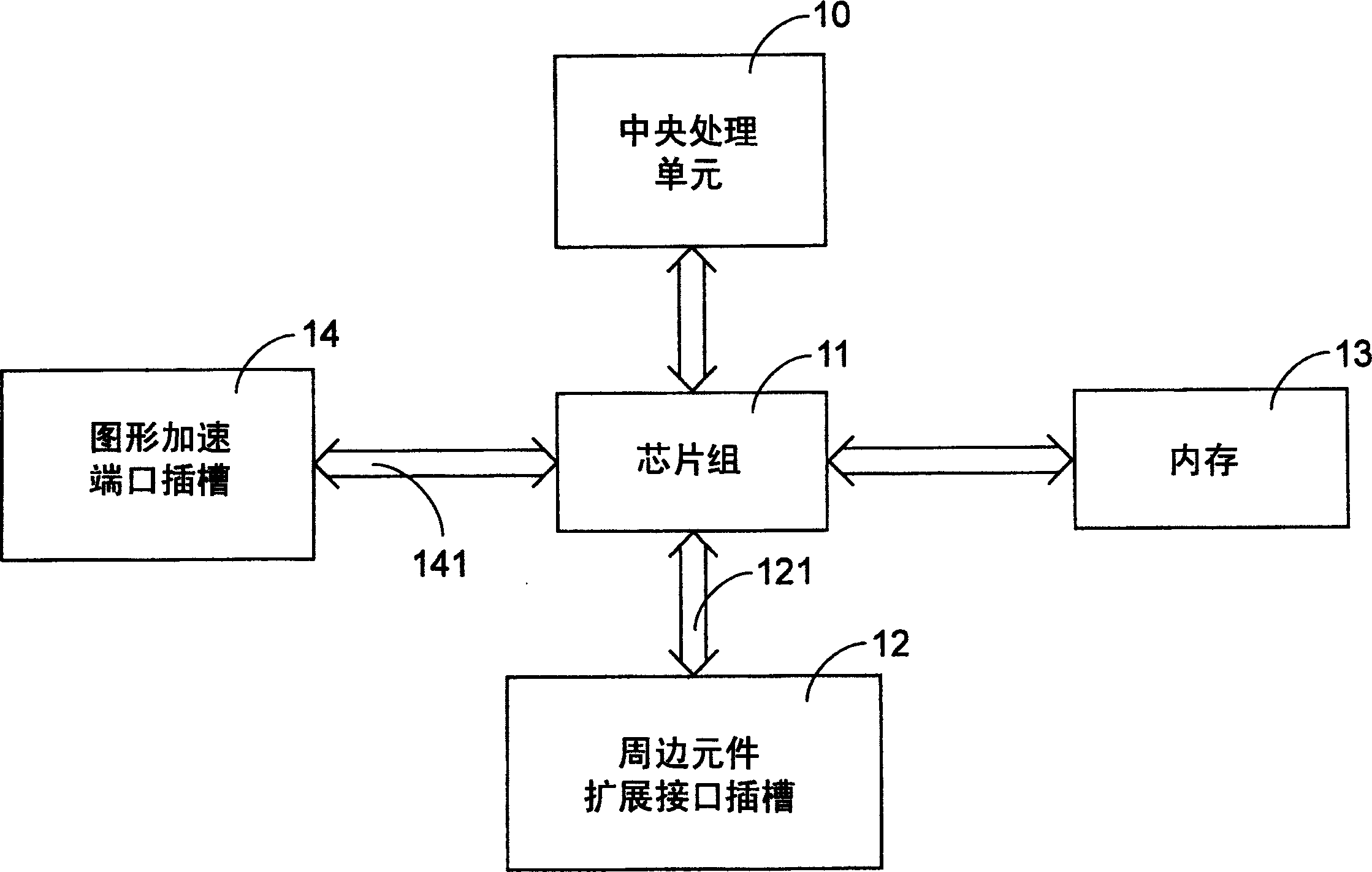
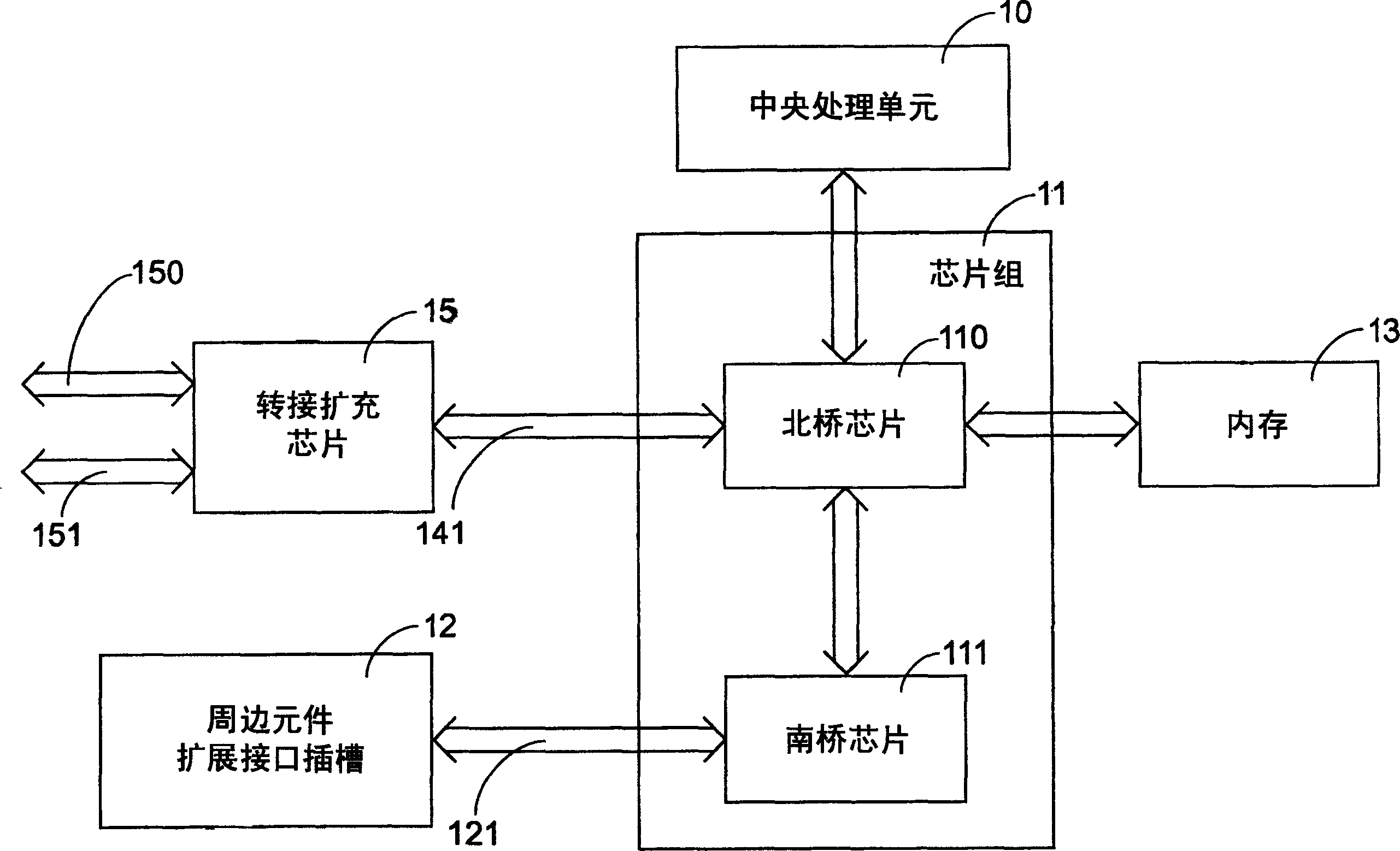
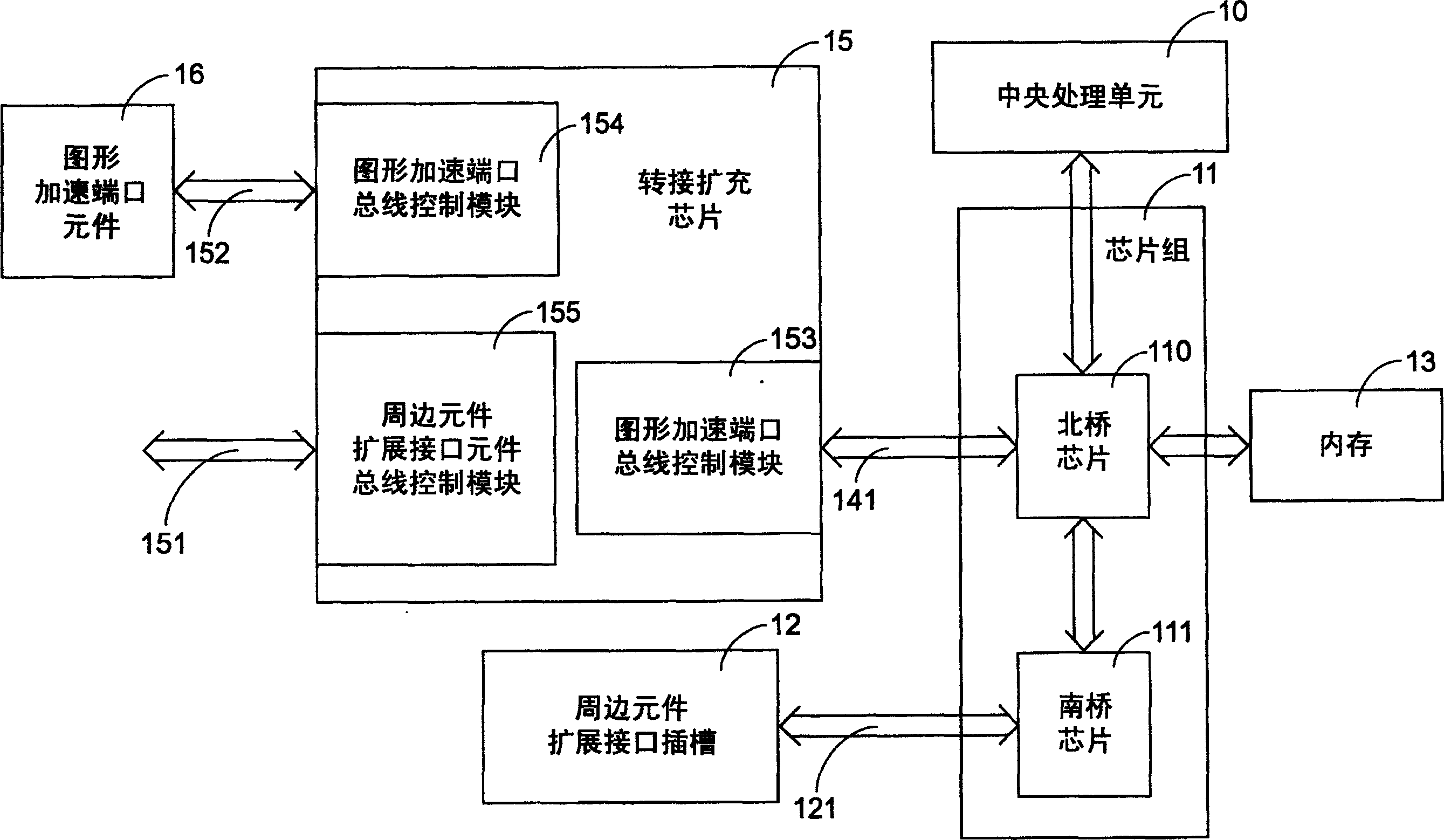
[0027] See Figure 2A , which is a schematic functional block diagram of a system in a preferred embodiment of the present invention. The chip set 11 connected to the central processing unit 10 is usually composed of a north bridge chip 110 and a south bridge chip 111, wherein the south bridge chip 111 usually extends out A plurality of peripheral component expansion interface slots 12 (PCI slots) are used for various PCI peripheral components (PCI devices), and the north bridge chip 110 is connected with the memory 13 (memory). Wherein the south bridge chip 111 is to complete the connection with the peripheral component expansion interface slot 12 by a peripheral component expansion interface bus 121 (PCI bus), and to effectively utilize the graphic acceleration port bus 141 (AGP bus) that has on the north bridge chip 110 ), the present invention replaces th...


PUM


Abstract

The invention provides a connecting and extending device, applied to a computer with an operating system, and comprising: a first accelerated graphics port (AGP) bus control module; a second AGP bus control module;; and a peripheral component interface (PCI) bus control module, where the signal lines are connected between the first AGP and PCI bus control modules to transmit signals. It can make full use of the function of rapid data transmission of the AGP socket.

Description

technical field [0001] The invention relates to a switch expansion device, especially a switch expansion device applied to a computer system with an operating system. Background technique [0002] See figure 1 , which is a connection schematic diagram of some components on an existing computer motherboard, a chipset 11 connected to a central processing unit 10, which is also connected to peripheral component expansion interface slots 12 (PCIslot), memory 13 (memory) and The Accelerated Graphics Port (AGP) slot 14 is connected, and the bus connected between the chipset 11 and the peripheral component expansion interface slot 12 is called the peripheral component expansion interface bus 121 (PCI bus). The bus connected between the chipset 11 and the accelerated graphics port socket 14 is called the accelerated graphics port bus 141 (AGPbus). [0003] And in order to enable fast data transmission between the image display card inserted in the graphics acceleration port slot 1...

Claims


Application Information

Patent Timeline
IPC IPC(8): G06F13/14
Inventor 苏俊源赖瑾蔡兆爵蔡奇哲
Owner VIA TECH INC
Why Eureka
Try Eureka