Axial gap brushless DC motor

A brush DC motor, axial air gap technology, applied in synchronous motors with stationary armature and rotating magnets, electrical components, electromechanical devices, etc.

Inactive Publication Date: 2004-11-24
DEERE & CO
View PDF0 Cites 20 Cited by
  • Summary
  • Abstract
  • Description
  • Claims
  • Application Information

AI Technical Summary

Problems solved by technology

Therefore, despite the desirable performance of such machines, the

Method used


Image

  • Axial gap brushless DC motor
  • Axial gap brushless DC motor
  • Axial gap brushless DC motor

Examples


Embodiment Construction

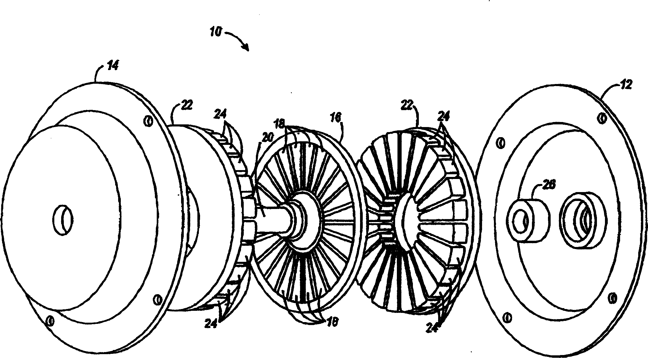
[0025] In general, the present invention provides a dual stator axial air gap brushless DC motor (eg, motor, alternator, etc.). The stator windings are embedded in slots formed on the stator, which has many advantages. The motor of the present invention is highly efficient and weighs significantly less than commercially available motors of the prior art. Because this design minimizes the use of expensive magnets and magnets, the weight savings translates into cost savings. The motor of the present invention has a high number of poles, with the result that a low speed, high torque motor is obtained. High power and high torque density allow the motor to directly drive loads in many applications, such as light vehicle traction drives. When complex converters are used, the motor of the present invention operates over a wide speed range without or minimizing the need for scaling.

[0026] figure 1 is an exploded perspective view of the dual stator axial air gap brushless DC mot...


PUM


Abstract

A dual stator axial gap DC brushless machine is provided with first and second stators having equal pole counts, a given pole arc, and a given slot arc. A rotor is disposed between the first and second stators, having a pole count greater than the first and second stators. The pole count ratio between each stator and the rotor is six to eight. The second stator has a given degree of angular displacement relative to the first stator less than, 3/4 , 1/2 or 1/4 the pole arc of the stators, but not less than the slot arc of the stators. Where the first and second stators each have a pole count of 18 and the rotor has a pole count of 24, the stator pole arc is 20 degrees, the rotor pole arc is 15 degrees, and the given degree of angular displacement is less than 20 degrees, 15 degrees, 10 degrees, or 5 degrees.

Description

[0001] Related application reference [0002] This application is a continuation-in-part of Application Serial No. 10 / 269,691 filed October 14,2002. technical field [0003] The present application relates to the field of motors, in particular to a double-stator axial air-gap brushless DC motor. Background technique [0004] There are many types of electrical machines (motors and / or alternators) known in the art. Each type of motor has different advantages and disadvantages for any particular application. Therefore, the type of motor generally employed depends on the application. One type of motor is a brushless permanent magnet DC motor. A typical brushless permanent magnet motor has relatively high power density because of its high efficiency and because the main losses occur in the stator, which is much easier to cool than the rotor. Expensive rare-earth magnets can provide stronger magnetic fields, which can effectively increase the power density of such motors, but ...

Claims


Application Information

Patent Timeline
IPC IPC(8): H02K16/04H02K21/24
CPCH02K21/24H02K16/04
Inventor O・豪甘B・B・普尔
Owner DEERE & CO
Why Eureka
Try Eureka