Current-drive circuit and apparatus for display panel

A current-driven, display panel technology, applied in static indicators, transportation and packaging, cathode ray tube indicators, etc., can solve the problem of reducing the response speed of the driving current, and achieve the effect of reducing voltage changes

Inactive Publication Date: 2004-12-01
RENESAS ELECTRONICS CORP
View PDF0 Cites 9 Cited by
  • Summary
  • Abstract
  • Description
  • Claims
  • Application Information

AI Technical Summary

Problems solved by technology

However, when the magnitude of the driving current becomes small, the response speed of the driving current in the MOS transistor circuit may decrease

Method used


Image

  • Current-drive circuit and apparatus for display panel
  • Current-drive circuit and apparatus for display panel
  • Current-drive circuit and apparatus for display panel

Examples


Embodiment Construction

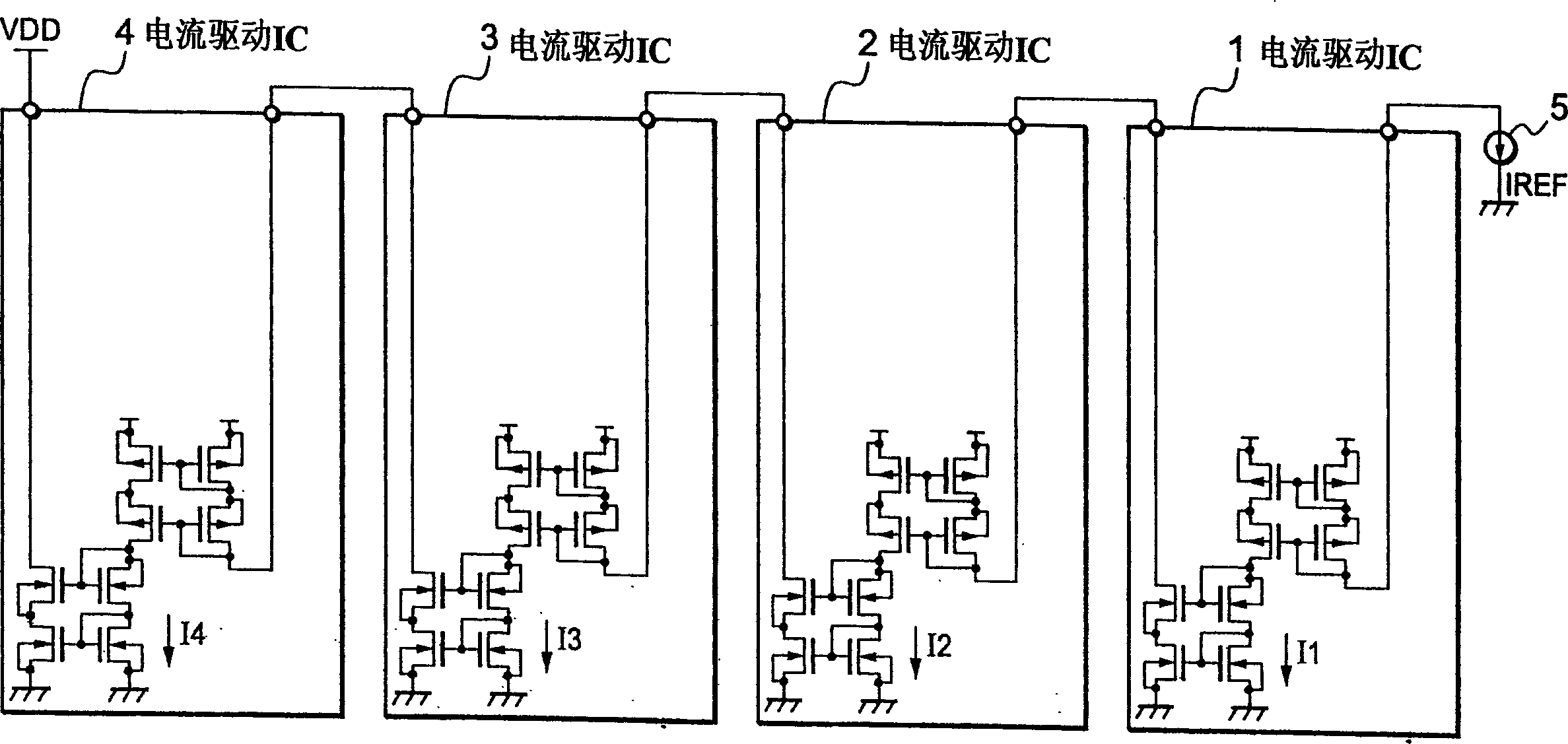
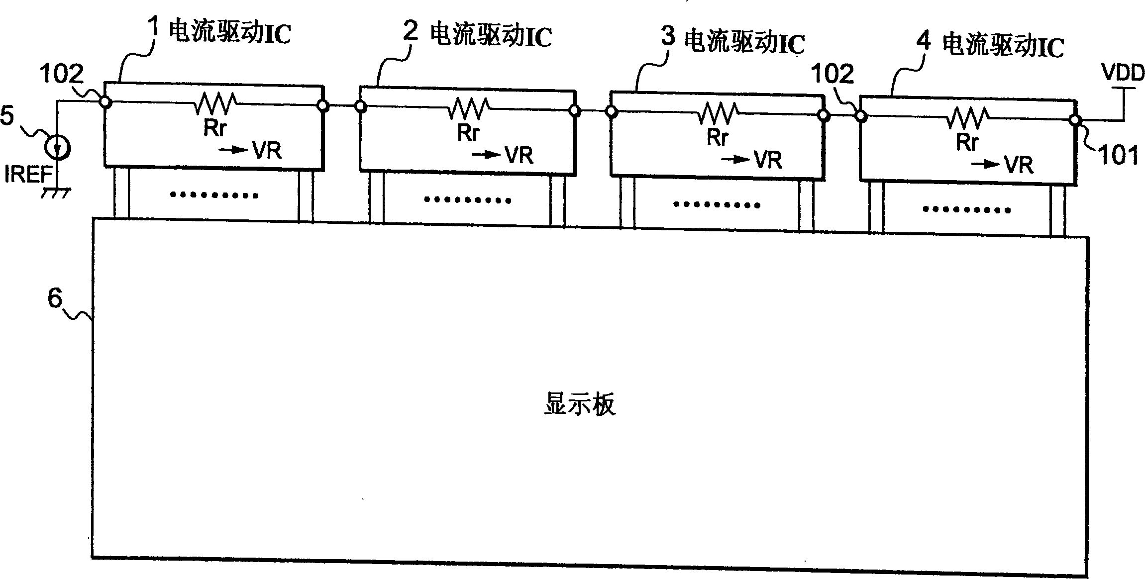
[0045] First, the outline of the present invention will be described. image 3 The geometric relationship between the current driving device of the present invention and a display panel driven by the current driving device (composed of a current driving IC) of the present invention is explained. like image 3 As shown, the current driving ICs 1 to 4 according to the present invention have reference resistors Rr respectively, these reference resistors Rr are connected in series, and further, one reference resistor Rr on the lowest potential side is connected to an external reference current source 5 . Assuming that the reference resistor Rr located between the two terminals 101 and 102 in each of the current driving ICs 1 to 4 enables the external reference current supplied by the external current source IREF to flow through the reference resistor Rr, at The two ends of the resistor Rr generate a voltage drop VR, so that the luminance of the light emitting elements of the displ...


PUM


Abstract

To equalize the intensity of light emitted by display elements on a display device, a plurality of current-drive circuits are connected in cascade through two terminals of each of the current-drive circuits, each comprising a reference current generation section including a reference resistor and a plurality of current drive sections. Reference current sunk by an external reference current source causes a voltage drop across the reference resistor, and the voltage drop is applied across a current adjustment resistor. In response to an image signal, the current-drive circuit outputs current, determined by multiplying each of a plurality of internal reference currents by an optional factor and summing the resulting currents to the display elements. Since the magnitude of the internal reference current flowing inside the current-drive circuit can be varied by varying the value of the current adjustment resistor, gamma correction can be applied to drive current with high accuracy.

Description

technical field [0001] The present invention relates to current drive circuits and devices for display panels, and more particularly to current drive circuits and devices that allow integration of display elements on display panels to improve the uniformity of luminous emission intensity. Background technique [0002] In recent years, with the advancement of microprocessing technology, semiconductor elements have become smaller, and LSIs (Large Scale Integration) integrating such semiconductor elements have become larger. For example, in a display device such as a liquid crystal display device, an output circuit provided in a driver circuit receives 8-bit digital data for displaying 1 pixel and generates a voltage for displaying a 2-dimensional image of 256 grayscales in order to drive a data line , so that this voltage is applied to the liquid crystal and drives the liquid crystal, enabling the liquid crystal display panel to display 16,770,000 colors. [0003] That is, wh...

Claims


Application Information

Patent Timeline
Patent Type & Authority Applications(China)
IPC IPC(8): G09G3/20G09G3/30G09G3/36G09G5/00
CPCG09G2310/027G09G2310/0272G09G2320/0233G09G3/3688G09G2320/0276B65G53/04B65G53/34B65G2201/045B65G2812/1641
Inventor 佐伯穣
Owner RENESAS ELECTRONICS CORP
Why Eureka
Try Eureka