
Assembly structure of liquid-crystal displaying device

A liquid crystal display and component structure technology, applied in the direction of instruments, nonlinear optics, optics, etc., can solve the problems of structural stability, buckling stability change, increased cost, time-consuming and labor-intensive, etc., to achieve high structural stability and improve stability Degree, the effect of meeting the cost

Inactive Publication Date: 2004-12-08
ARIMA DISPLAY
View PDF0 Cites 6 Cited by
  • Summary
  • Abstract
  • Description
  • Claims
  • Application Information

AI Technical Summary

Problems solved by technology

[0005] However, the above-mentioned assembly method has many disadvantages
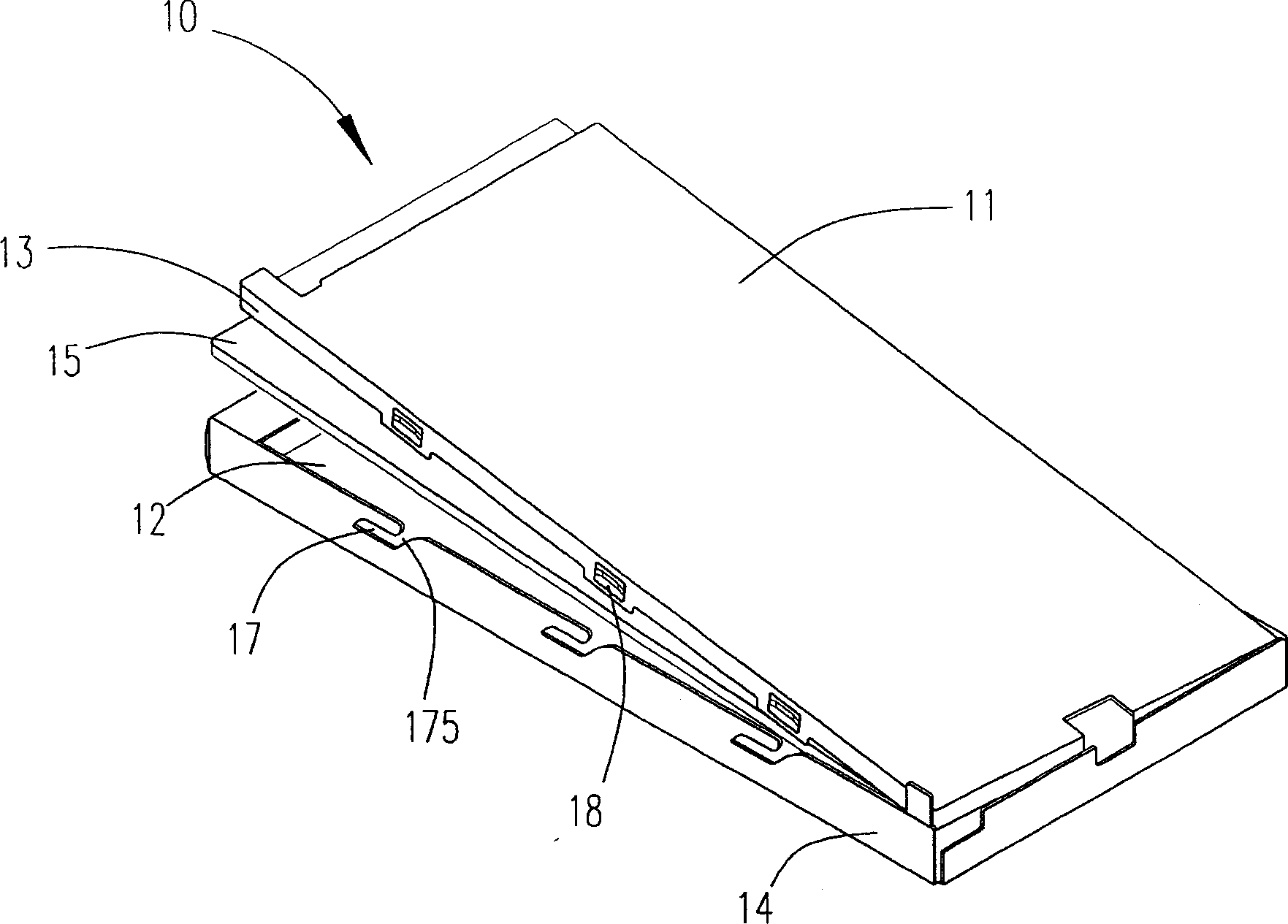
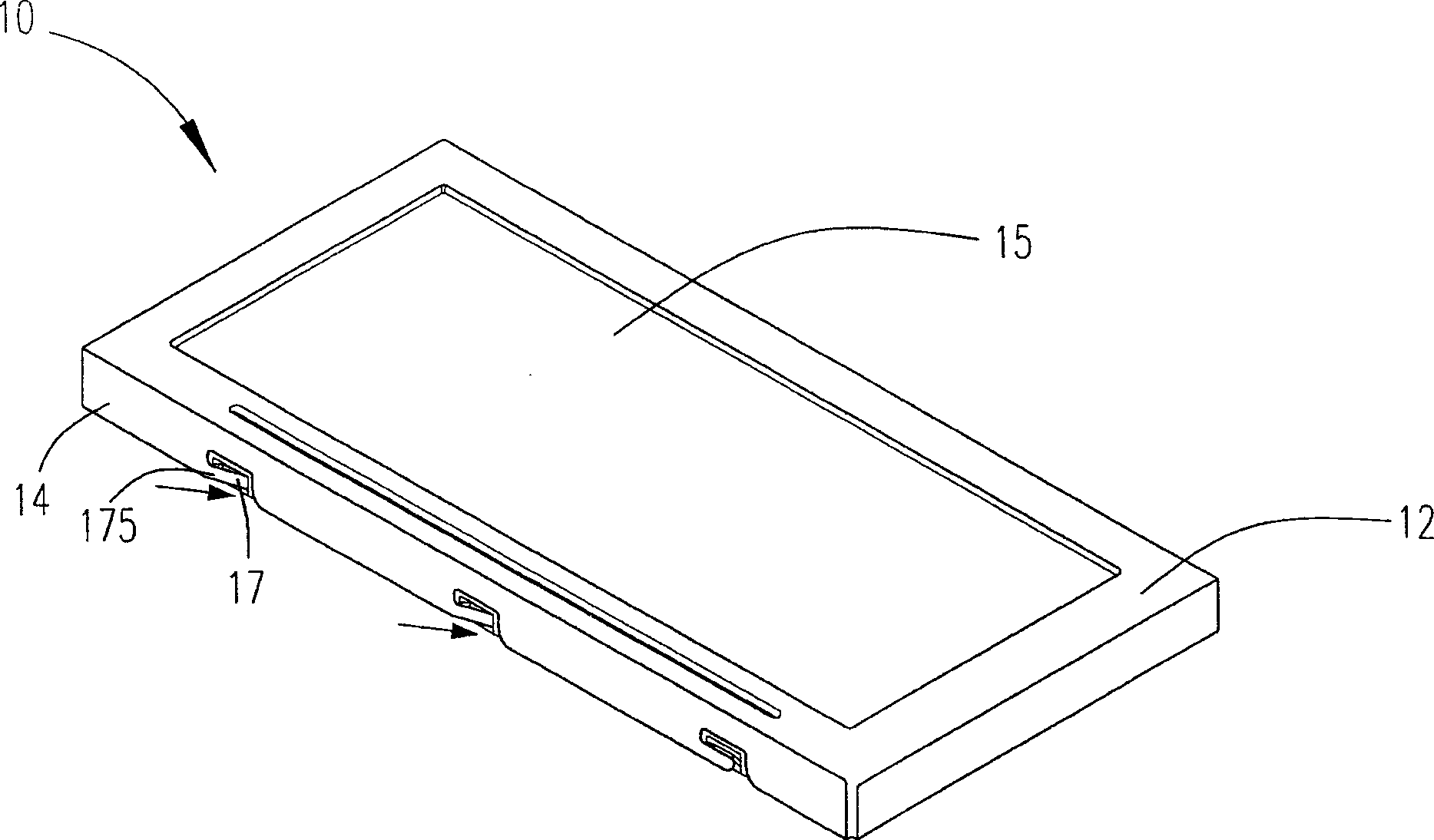
First, in order to keep the display panel intact and avoid damage to the liquid crystal display main body 15 during operation, it is necessary to adopt reverse assembly when assembling, that is, turn the entire LCD assembly 10 over for assembly, but after the assembly is completed, the LCD assembly must be reassembled. 10 Turn it over, that is, the platform must be moved on the production line, which is quite time-consuming and laborious, and it is also very inconvenient
In addition, if a mass production is to be carried out with a turntable mold, it is necessary to make different sizes of turntable molds according to the size of each LCD module 10, which is not only very uneconomical, but also increases the production cost.
In addition, the fixed rotating leg 17 is quite easy to break due to excessive force or repeated bending at its rotating leg 175, which affects the structure of the entire LCD assembly 10.
What's more, in the process of inserting and hooking the fixed turning foot 17 into its corresponding fixing hole 18, the angle of each turning foot is not constant, and the depth inserted into the fixing hole 18 is also different. The entire LCD assembly 10 is fixed, but in fact, the structural stability of each LCD assembly 10 will change due to the engagement stability between the fixed turning pin 17 and the fixing hole 18. In the field of LCD assemblies that are very particular about structural stability , will seriously affect the quality control of the structural stability of LCD components

Method used


Image

  • Assembly structure of liquid-crystal displaying device
  • Assembly structure of liquid-crystal displaying device
  • Assembly structure of liquid-crystal displaying device

Examples


Embodiment Construction

[0045] The component structure of the liquid crystal display of the present invention will be fully understood from the following embodiments, so that those skilled in the art can complete it. However, the implementation of the present invention is not limited by the following embodiments. .

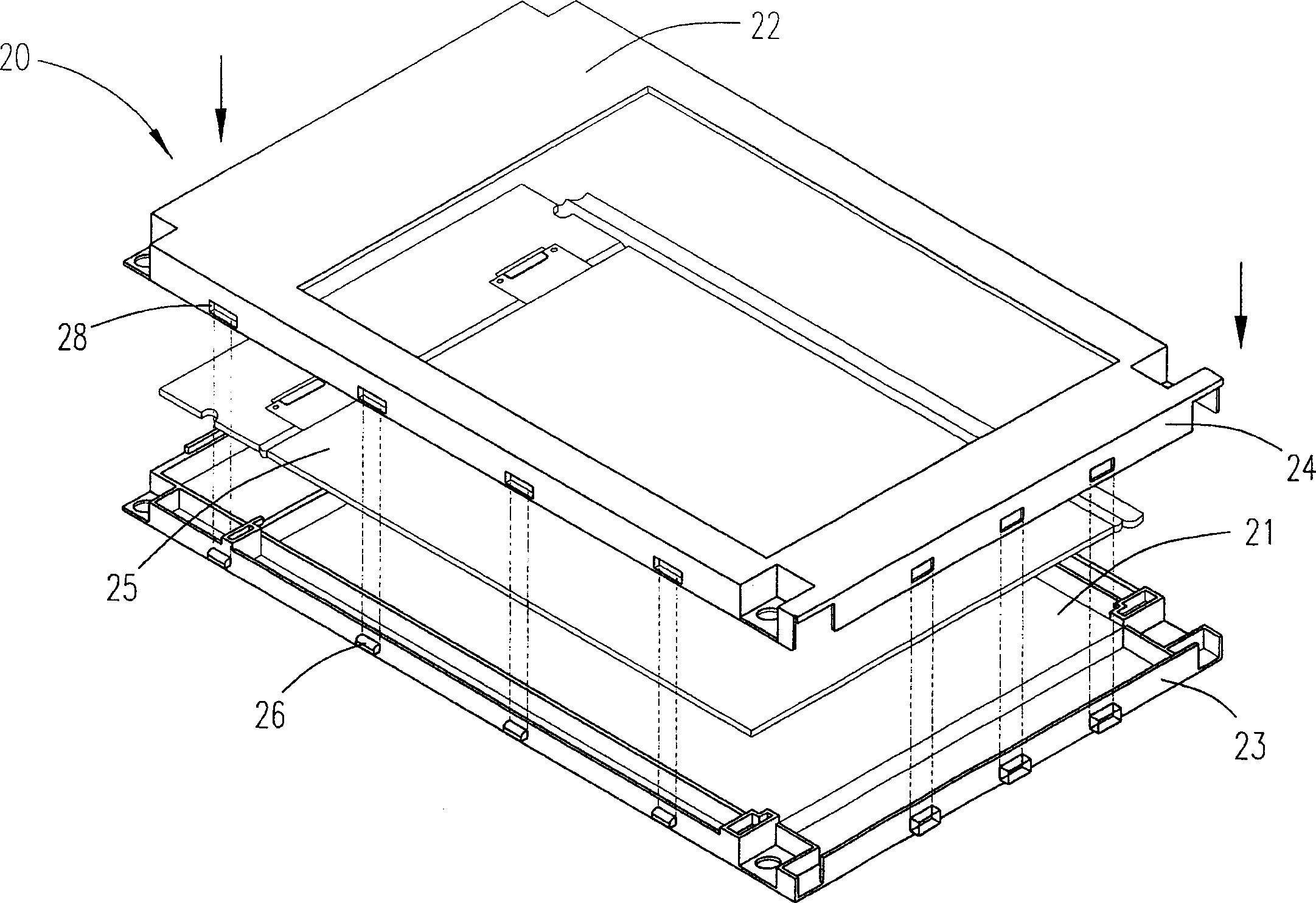
[0046] See image 3 , Which is a schematic diagram of the assembly method of the LCD component structure of a preferred embodiment of the present invention. The LCD assembly 20 is mainly composed of a base 21, a cover 22, a liquid crystal display body 25, a plurality of fixing holes 28, and a plurality of protruding members 26. The base 21 includes a first frame 23 for placing and accommodating the liquid crystal display main body 25. The cover 22 includes a second frame 24, which is covered on the base 21 by the joint between the second frame 24 and the first frame 23. In addition, the second frame 24 is also provided with multiple A fixed hole 28. A plurality of protruding members 26 are f...


PUM


Abstract

A structure comprises a liquid crystal display body, a base including the first frame for placing and containing display body, a cover including the second frame integrated with the first one for covering on the base, multiple fixing hole surrounding periphery of the second frame, multiple concave opening at bottom edge of the second frame, multiple projection component fixed on the first frame periphery corresponding to position of multiple fixing hole and checked together with these holes and multiple positioning block component fixed at bottom edge of the first frame corresponding to position of multiple concave opening for protecting display body from damage by over pressing down of the second frame.

Description

(1) Technical field [0001] The present invention relates to a liquid crystal display structure, in particular to a component structure of a liquid crystal display. (2) Background technology [0002] With the development of technology and the continuous improvement of people's requirements, people are becoming more and more dissatisfied with the disadvantages of the original traditional cathode ray tube (Cathode Ray Tube; CRT) display of large size, large weight, and large energy consumption. Especially in portable, miniaturized, and low-power-consumption applications, people expect the emergence of flat-panel displays with small size, light weight, and low power consumption. Driven by this demand, liquid crystal display (Liquid Crystal Display; LCD) came into being. Due to the advantages of liquid crystal display (LCD) in light, thin, short, low power consumption, no radiation, flat right-angle display and stable image without flickering, it has occupied a considerable market und...

Claims


Application Information

Patent Timeline
IPC IPC(8): G02F1/1333
Inventor 卓聪杰
Owner ARIMA DISPLAY
Learn More