Reference electrode clamp used for biological resistance, impedance, electric potential measurement

A technology of potential measurement and reference electrode, which is applied in the field of medical devices, can solve the problems of human discomfort, viscose loss of viscosity, application of certain external force, etc., and achieve the effect suitable for repeated use

Inactive Publication Date: 2004-12-22
ZHEJIANG UNIV
View PDF2 Cites 10 Cited by
  • Summary
  • Abstract
  • Description
  • Claims
  • Application Information

AI Technical Summary

Problems solved by technology

[0002] The utility model patent 93227306.8 proposes a contact electrode of an electronic therapy devi

Method used


Image

  • Reference electrode clamp used for biological resistance, impedance, electric potential measurement

Examples


Embodiment Construction

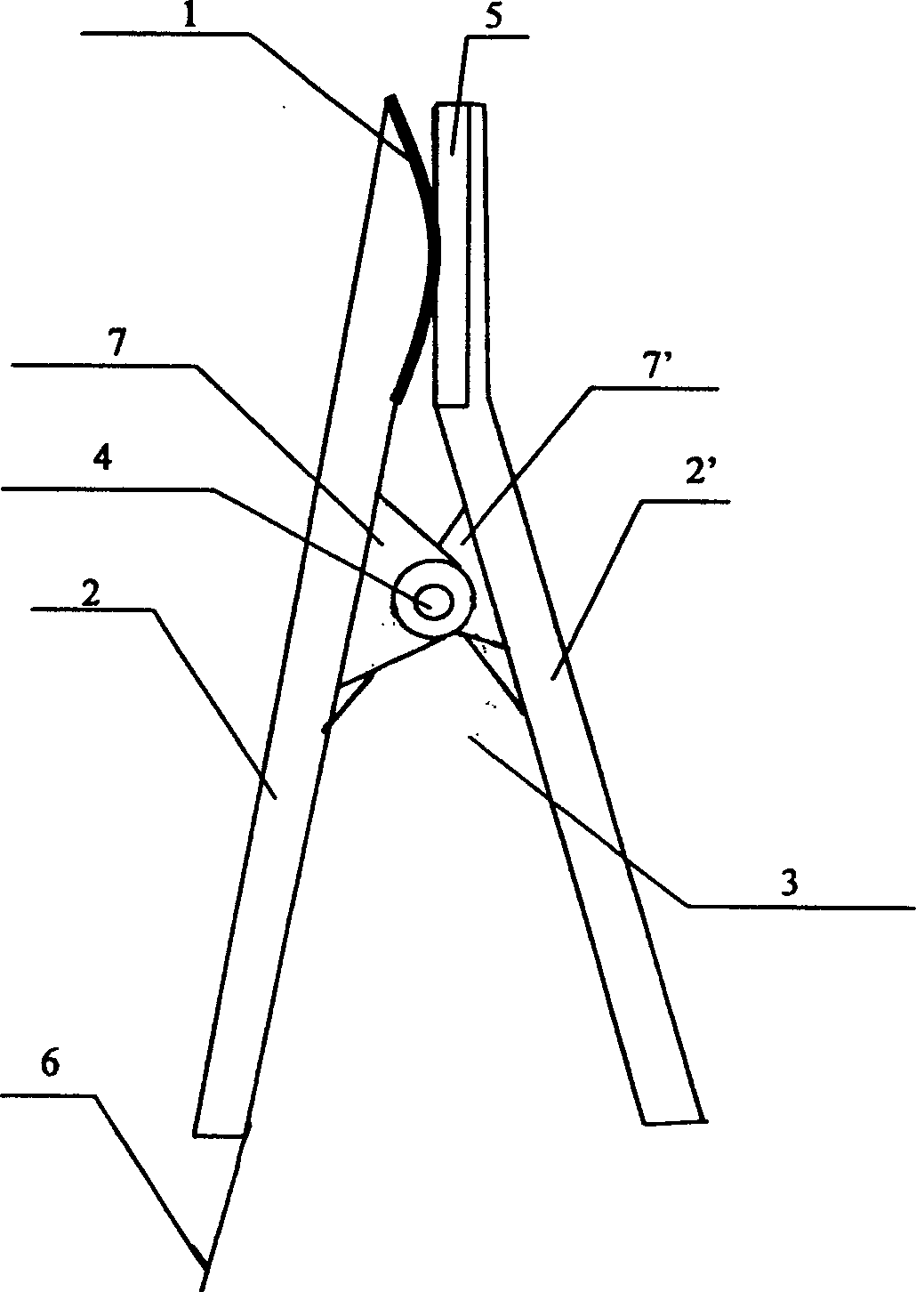
[0011] As shown in the accompanying drawings, the present invention includes two clamping members 2, 2' of a pair of fins 7, 7' protruding inwards in the middle, the fin holes are connected by a clamp shaft 4, and the clamp spring 3 is enclosed within the two clamping members. On the rotating shaft 4 of the wings 7, 7', one end of the clamp spring 3 is fixed on the inner surface of a clamping member 2, and the other end of the clamp spring 3 is fixed on the inner surface of another clamping member 2', so as to realize a pair of clamping The opening and closing movement of the components 2 , 2 ′ around the clamp shaft 4 . An electrode 1 connected with a wire 6 is installed on the inner surface of the upper end of one clamping member 2 , and a non-conductive buffer pad is installed on the inner surface of the upper end of the other clamping member 2 ′ opposite to the electrode 1 .

[0012] The electrode 1 is a conductor with a raised surface, which can be a metal mesh or a solid...


PUM


Abstract

A reference electrode clamper used for measuring the biological resistance, impedance and potential is composed of two clamping jaws with central perforated fins, a rotary axle passing through the holes of said fins for connecting both clamping jaws, a spring on said rotary axle, and an electrode attached to inner surface of one clamping jaw. It can fix the electrode onto surface of human body.

Description

Technical field [0001] The invention relates to a medical device, in particular to a reference electrode clip for measuring biological resistance, impedance and potential. Background technique [0002] The utility model patent 93227306.8 proposes a contact electrode of an electronic therapy device. The electrode is fixed on the surface of the human body by glue. The human body brings discomfort. The utility model patent 95246280.X proposes an electrode of an electronic diagnosis and treatment device with a sheath, which also has the above-mentioned problems. Contents of the invention [0003] The object of the present invention is to provide a reference electrode clip for bio-resistance, impedance and potential measurement, which is used to inject measurement signals into the human body and form a loop together with the measurement electrodes. [0004] In order to achieve the above object, the technical scheme adopted in the present invention is as follows: [0005] It ...

Claims


Application Information

Patent Timeline
IPC IPC(8): A61B5/0408A61B5/055
Inventor 李江
Owner ZHEJIANG UNIV
Why Eureka
Try Eureka