

Dimming circuit for electromagnetic induction lamp
An electromagnetic induction lamp and dimming circuit technology, applied in the field of dimming circuit, can solve the problems of no dimming, long switching time, high temperature of MOS tube, etc.
- Summary
- Abstract
- Description
- Claims
- Application Information
AI Technical Summary
Problems solved by technology
Method used
Image

Examples
Embodiment Construction
[0030] The technical solutions of the present invention will be further described below in conjunction with the drawings and embodiments.
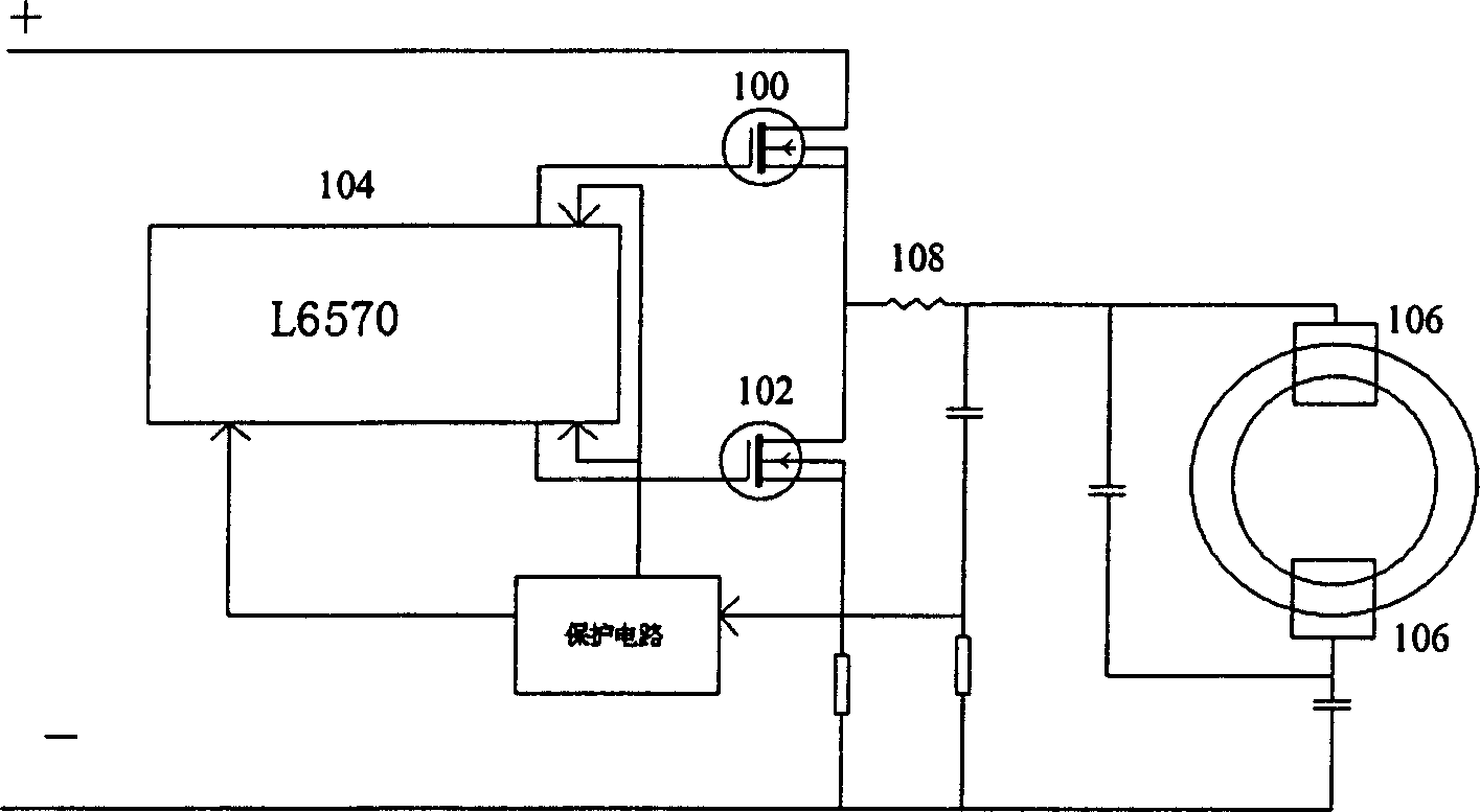
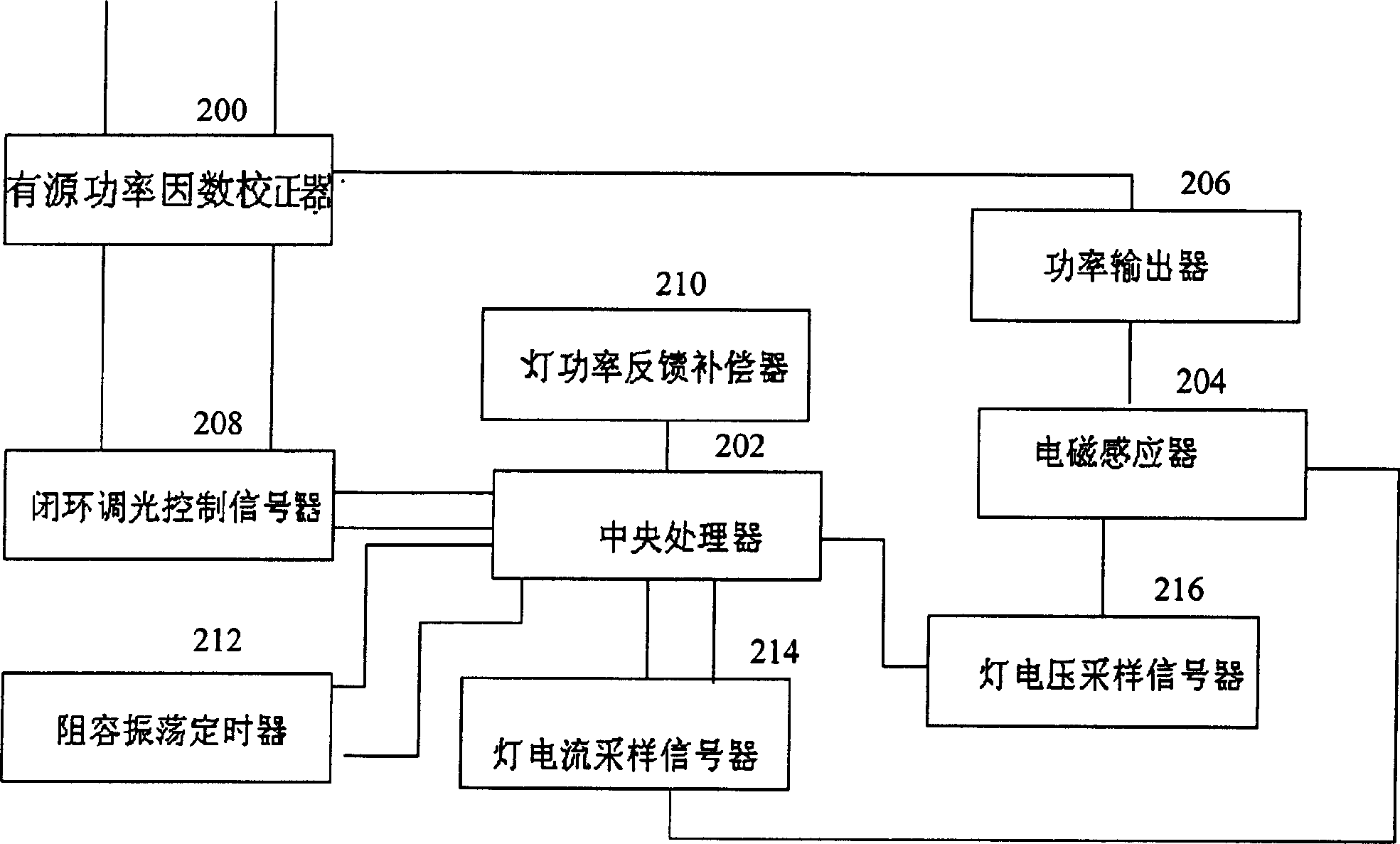
[0031] figure 2 It is a block diagram of a part of the circuit of the electromagnetic induction lamp of the present invention, such as figure 2 As shown, the dimming circuit of the present invention is connected to the electromagnetic induction lamp circuit, and the electromagnetic induction lamp circuit should at least include an active power factor corrector 200, a central processing unit 202, an electromagnetic inductor 204 and a power output device 206. figure 2 In the illustrated embodiment, the active power factor corrector 200 is connected to a power output device 206, which provides a stable DC voltage for subsequent circuits. The electromagnetic inductor 204 is also connected to the power output device 206, and also connected to the electromagnetic induction lamp tube (not shown in the figure). The power output device 206 is ...
PUM
 Abstract
Description
Claims
Application Information