Lifting pole of lighting vehicle

A technology for lifting columns and lighting vehicles, which is applied to lifting frames, lifting devices, searchlight transportation, etc., can solve the problems of danger, insecurity, heavy weight, etc., and achieve the effect of stable and free lifting, easy installation and disassembly, and simple structure.

Inactive Publication Date: 2005-01-05
周京舟
View PDF0 Cites 24 Cited by
  • Summary
  • Abstract
  • Description
  • Claims
  • Application Information

AI Technical Summary

Problems solved by technology

[0002] At present, the known lifting columns of lighting vehicles using pneumatic springs fix the lock and hook respectively on the first lifting cylinder and the last lifting cylinder and lock them to compress the pneumatic spring. When the hook and lock are opened, the lifting cylinder rises. , at this time, under the action of the pneumatic spring, several lifting cylinders rise rapidly. Because the top of the lifting cylinder is fixed with a lighting lamp, the weight is heavy, so the lighting lamp will swing left and right when it rises rapidly. In addition, when the surrounding environment is not clearly seen , Accidents may occur if you accidentally open the hook, which is very dangerous and extremely unsafe.

Method used


Image

  • Lifting pole of lighting vehicle
  • Lifting pole of lighting vehicle
  • Lifting pole of lighting vehicle

Examples


Embodiment Construction

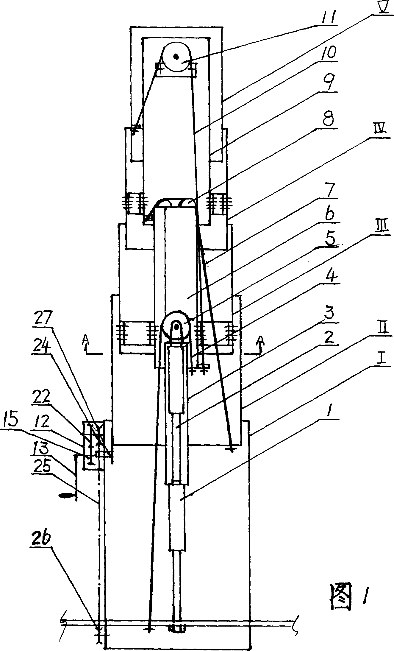
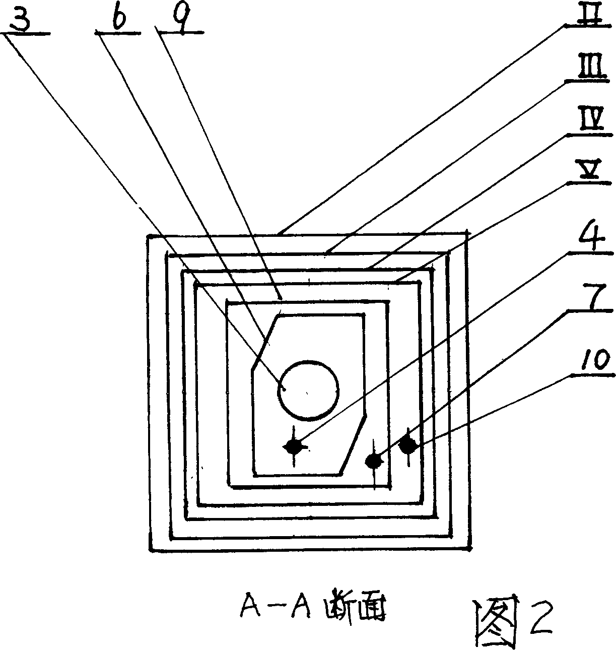
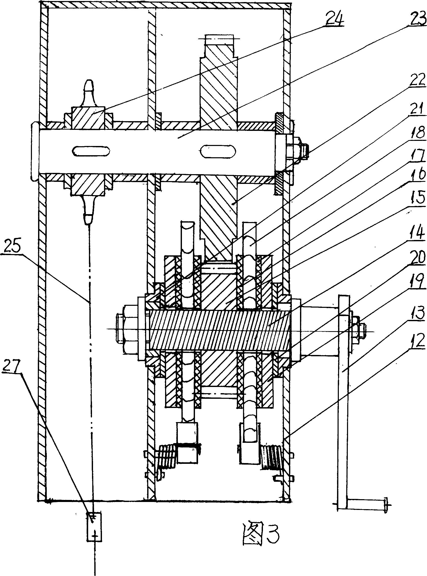
[0012] In order to further understand the characteristics and functions of the present invention, the following embodiments are given as examples, and detailed descriptions are as follows with reference to the accompanying drawings, please refer to FIGS. 1-3 .

[0013] As shown in Figure 1: the lifting column of the lighting vehicle consists of two pneumatic springs 1 and 2 connected by threads at the head and tail, five lifting cylinders I, 11, III, IV, V, and three inner sleeves of different shapes 3, 6, 9. Three sets of pulleys 5, 8, 11, three steel wire ropes 4, 7, 10 and a hand-cranking device, three inner circle sleeves are set outside the pneumatic springs 1 and 2 and fixed with pressure plates and screws, the piston end of the pneumatic spring 1 and One end of the wire rope 4 is respectively fixed on the bottom of the 1st section lifting cylinder 1, and the other end of the wire rope 4 is fixed on the lower end of the oblique hexagonal inner sleeve 6 around the pulley 5...


PUM


Abstract

A vertical lifting column for lighting vehicle is composed oftwo pneumatic springs, 5 lifting pipes, 3 internal sleeves, 3 pulley sets, 3 steel cables and a manual rocker fixed to the first lifting pipe for driving the lifting up or lowering down of said lifting column.

Description

Technical field: [0001] The invention relates to a stable lifting, safe and reliable lighting vehicle lifting column. Background technique: [0002] At present, the known lifting columns of lighting vehicles using pneumatic springs fix the lock and hook respectively on the first lifting cylinder and the last lifting cylinder and lock them to compress the pneumatic spring. When the hook and lock are opened, the lifting cylinder rises. , at this time, under the action of the pneumatic spring, several lifting cylinders rise rapidly. Because the top of the lifting cylinder is fixed with a lighting lamp, the weight is heavy, so the lighting lamp will swing left and right when it rises rapidly. In addition, when the surrounding environment is not clearly seen , Unintentionally opening the hook just may cause an accident, which is very dangerous and extremely unsafe. At the same time, if the lifting cylinder is to be lowered, the handle must be pulled hard to press down to compress...

Claims


Application Information

Patent Timeline
Patent Type & Authority Applications(China)
IPC IPC(8): B60P3/18B66F7/02
Inventor 周京舟
Owner 周京舟
Why Eureka
Try Eureka