Equipment for rising and falling headlamp on locomotive

A lifting device and headlight technology, which is applied to railway vehicle lighting devices, signal devices, vehicle parts, etc., can solve the problems of damage to interior decoration components, difficulty in repairing headlight lamps and lanterns, and inability to reach the headlight box with hands, and achieves convenient operation. , the effect of short maintenance cycle

Inactive Publication Date: 2005-01-12
顾群
View PDF0 Cites 3 Cited by
  • Summary
  • Abstract
  • Description
  • Claims
  • Application Information

AI Technical Summary

Problems solved by technology

[0002] The headlight devices of existing various types of electric power and internal combustion locomotives are all installed and fixed in the headlight box on the front top of the locomotive driver's cab. It is difficult to clean the light bulb in the light box, clean the light bowl, or check the failure of the headlight lamp. Due to the limitation of

Method used


Image

  • Equipment for rising and falling headlamp on locomotive
  • Equipment for rising and falling headlamp on locomotive
  • Equipment for rising and falling headlamp on locomotive

Examples


Embodiment Construction

[0012] The present invention will be further described below in conjunction with drawings and embodiments.

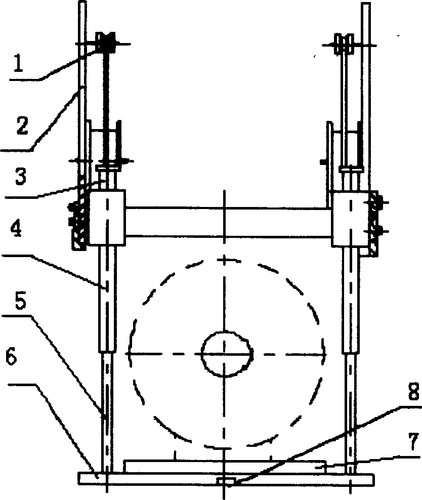
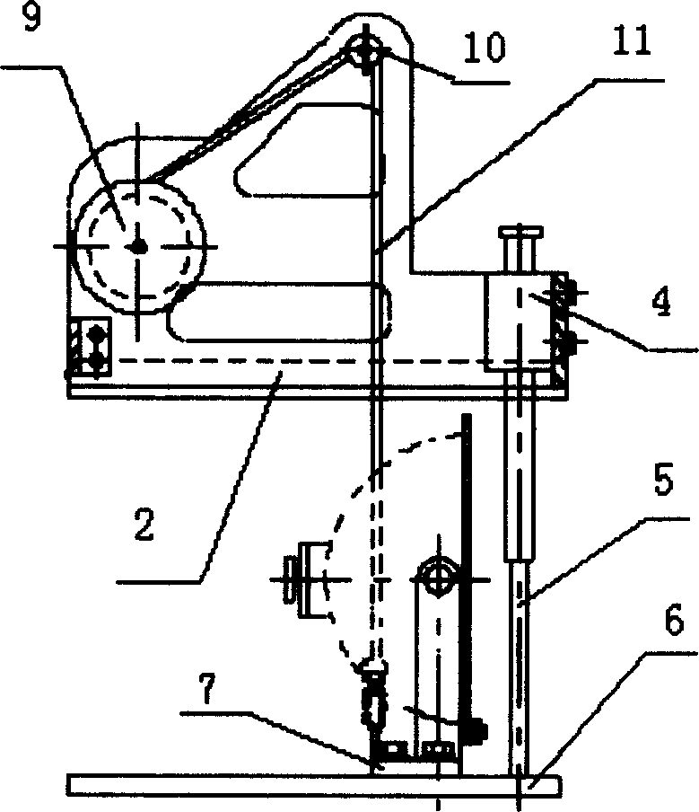
[0013] Such as figure 1 , 2 As shown, the locomotive headlight lifting device is composed of four parts: a lifting mechanism 1, a fixed support 2, a guide mechanism 4, and a movable support 6.

[0014] Described lifting mechanism 1 is to comprise spring wheel 9, pulley 10, wire rope 11. Spring wheel 9 and pulley 10 are installed on the fixed support 2, and one end of wire rope 11 is fixed on the spring wheel 9 and after winding around pulley 1 more than 2 circles again, its end is fixed on the movable support 6. Due to the effect of spring wheel 9 internal springs, wire rope 10 is in tension state all the time, and movable support 6 is subjected to upward pulling force all the time by pulley 10, has balanced the gravity of movable support 6 together with guide mechanism 4. Due to the effect of the guide mechanism 4, the movable support 6 can move up and down along th...


PUM


Abstract

A vertically moving unit for the headlight of locomotive is composed of a lifting mechanism which may be pulley one, rack bar one, or hydraulic one, fixed supporting frame, guide mechanism and movable supporting frame connected to said fixed one via guide mechanism.

Description

technical field [0001] The invention relates to a headlight lifting device, in particular to a locomotive headlight lifting device. Background technique [0002] The headlight devices of existing various types of electric power and internal combustion locomotives are all installed and fixed in the headlight box on the front top of the locomotive driver's cab. It is difficult to clean the light bulb in the light box, clean the light bowl, or check the failure of the headlight lamp. Due to the limitation of the size of the headlight box, hands cannot reach into the headlight box to perform related operations. After completing the above work, part of the interior decoration components at the top of the locomotive driver's cab will also be removed when the headlight device is disassembled as a whole, causing these interior decoration components to be damaged. Contents of the invention [0003] The present invention aims to ove...

Claims


Application Information

Patent Timeline
IPC IPC(8): B61D29/00
CPCB61L15/02B60Q1/05B61D29/00
Inventor 李涛
Owner 顾群
Why Eureka
Try Eureka