Auxiliary suction inlet of vacuum sweeper

A vacuum cleaner and suction port technology, applied in the directions of vacuum cleaners, suction nozzles, handles, etc., can solve the problems of easy loss, complicated operation, small size of the auxiliary suction port 10, etc., and achieve the effect of convenient operation.

Inactive Publication Date: 2005-01-19
LG ELECTRONICS (TIANJIN) APPLIANCES CO LTD
View PDF0 Cites 2 Cited by
  • Summary
  • Abstract
  • Description
  • Claims
  • Application Information

AI Technical Summary

Problems solved by technology

[0004] But the auxiliary suction port of the above-mentioned existing vacuum cleaner has the following disadvantages: when it utilizes the auxiliary suction port 10 to clean, after the extension pipe 7 is separated from the operating handle part 5, the connecting part 12 of the auxiliary suction port 10 is inserte...

Method used


Image

  • Auxiliary suction inlet of vacuum sweeper
  • Auxiliary suction inlet of vacuum sweeper
  • Auxiliary suction inlet of vacuum sweeper

Examples


Embodiment Construction

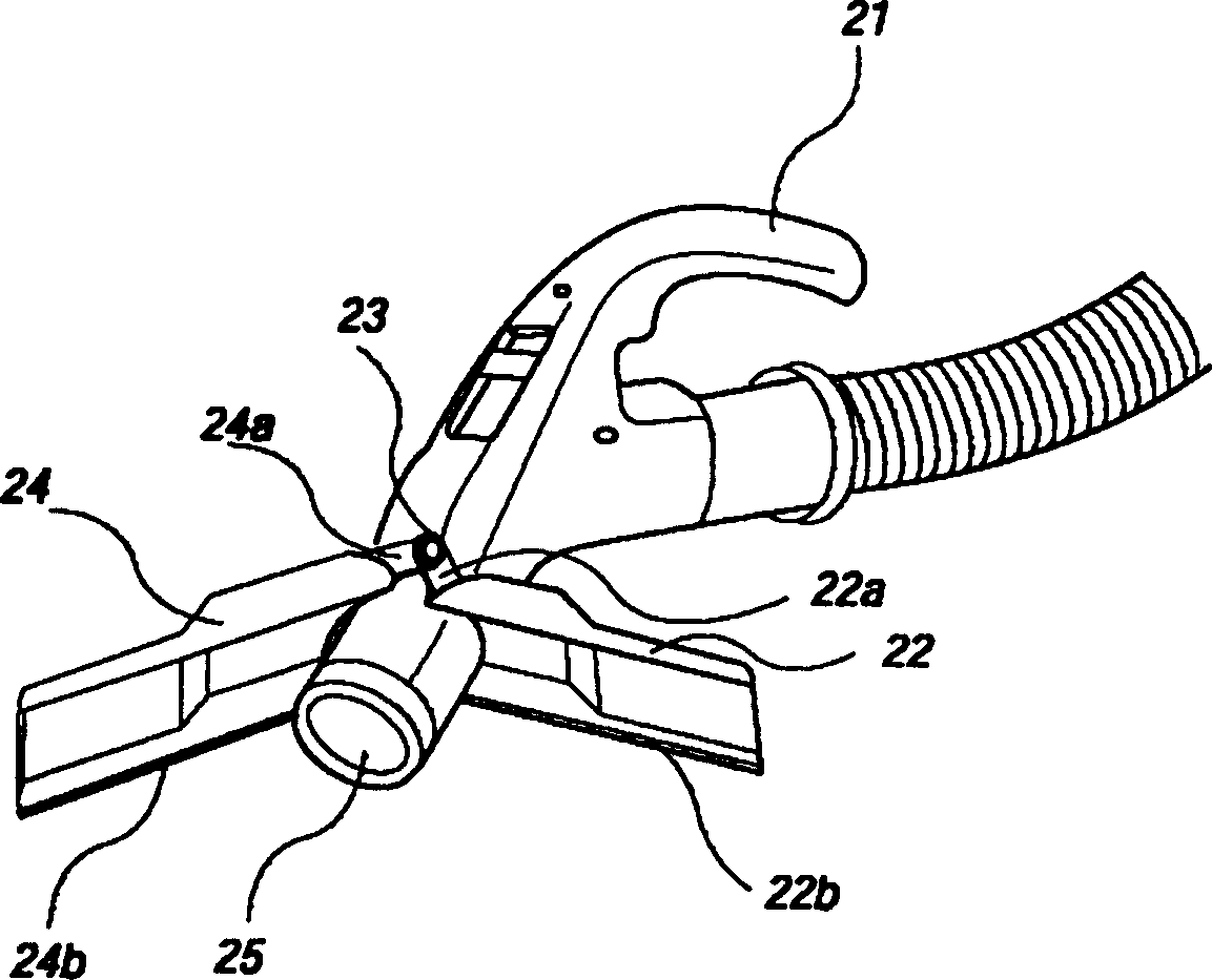
[0017] image 3 Shown is a schematic diagram of the three-dimensional structure of the auxiliary suction port of the embodiment of the present invention, Figure 4 yes image 3 Schematic diagram of the use status of the auxiliary suction port shown. As shown in the figure, a pair of blades 22 and 24 of the auxiliary suction port 20 of the present invention are assembled with the rotating shaft 23 at the front end of the handle portion 21, so that the inflow port 27 at the opening communicates with the suction port 25 of the handle portion; the auxiliary suction port 20 includes: a first blade 22 and a second blade 24 assembled symmetrically on the basis of the rotating shaft 23, the rear sides of the first blade 22 and the second blade 24 are respectively extended with connecting hinge pieces 22a and 24a, and the inner wall of the first blade 22 The upper and lower side edges are provided with hanging grooves 22b, and the outer walls of the upper and lower side edges of the ...


PUM


Abstract

The invention provides an auxiliary suction inlet of the vacuum aspirator. It comprises a handle portion having a rotation axis on the side of the front, a first blade and a second blade symmetrical installed by making the turning axis as benchmark, a pair of connection butt hinge pieces extends separately from the first blade and the second blade, which can be installed correspondently on the turning axis by turning. The first and the second blade, are bonded together to form integral front end opening structure, turns around the turning axis. Auxiliary inlet mounting on the front end of the handle make it possible for not keeping the auxiliary suction inlet additionally. It has convenient operation and can be used at any moment, there is no need to keep it additionally, thus avoids loss easily problem.

Description

1. Technical field [0001] The invention relates to purification equipment, in particular to an auxiliary suction port of a vacuum cleaner which is rotatably installed on a handle and is convenient to use. 2. Background technology [0002] Such as figure 1 As shown in the structure of the existing vacuum cleaner, the vacuum cleaner includes: a suction device for sucking indoor air; a body 1 for collecting and accommodating foreign matter from the air sucked by the suction device is provided inside; the suction device of the body 1 The suction nozzle 9 that produces suction suction room air. The structure between the fuselage 1 and the suction nozzle 9 comprises in order: a suction hose (hose) 3 made of soft material; an operating handle part 5 connected to the end of the suction hose 3; The extension pipe 7 of the nozzle 9 is designed so that the suction generated by the fuselage 1 is transmitted to the suction nozzle 9 . This suction nozzle 9 bottom surfaces are flat plat...

Claims


Application Information

Patent Timeline
IPC IPC(8): A47L9/00A47L9/02A47L9/32
Inventor 金贤佑
Owner LG ELECTRONICS (TIANJIN) APPLIANCES CO LTD
Why Eureka
Try Eureka