Structure of centrifugal switch

A centrifugal, switching technology, applied in electrical switches, electrical components, circuits, etc., can solve problems such as noise generation, and achieve the effect of improving reliability

Inactive Publication Date: 2005-01-19
LG ELECTRONICS (TIANJIN) APPLIANCES CO LTD
View PDF0 Cites 3 Cited by
  • Summary
  • Abstract
  • Description
  • Claims
  • Application Information

AI Technical Summary

Problems solved by technology

[0011] The centrifugal switch 1 of the prior art produces noise when the circuit is disconnected, that is, when the rotating speed of the motor shaft 7 increases, and when the centrifugal force caused acts on the centrifugal brake 4, the head end of the slider 3 will be in contact with the hollow shaft 2. The 210 faces of the flanges collide and produce noise

Method used


Image

  • Structure of centrifugal switch
  • Structure of centrifugal switch
  • Structure of centrifugal switch

Examples


Embodiment Construction

[0029] The structure of the centrifugal switch of the present invention will be further described in detail below in conjunction with the accompanying drawings and specific embodiments:

[0030] In the following description, the same parts as the prior art refer to the prior art and use the same symbols.

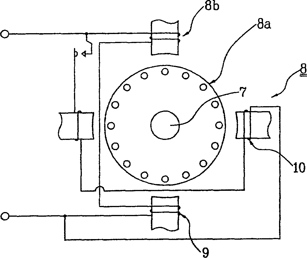
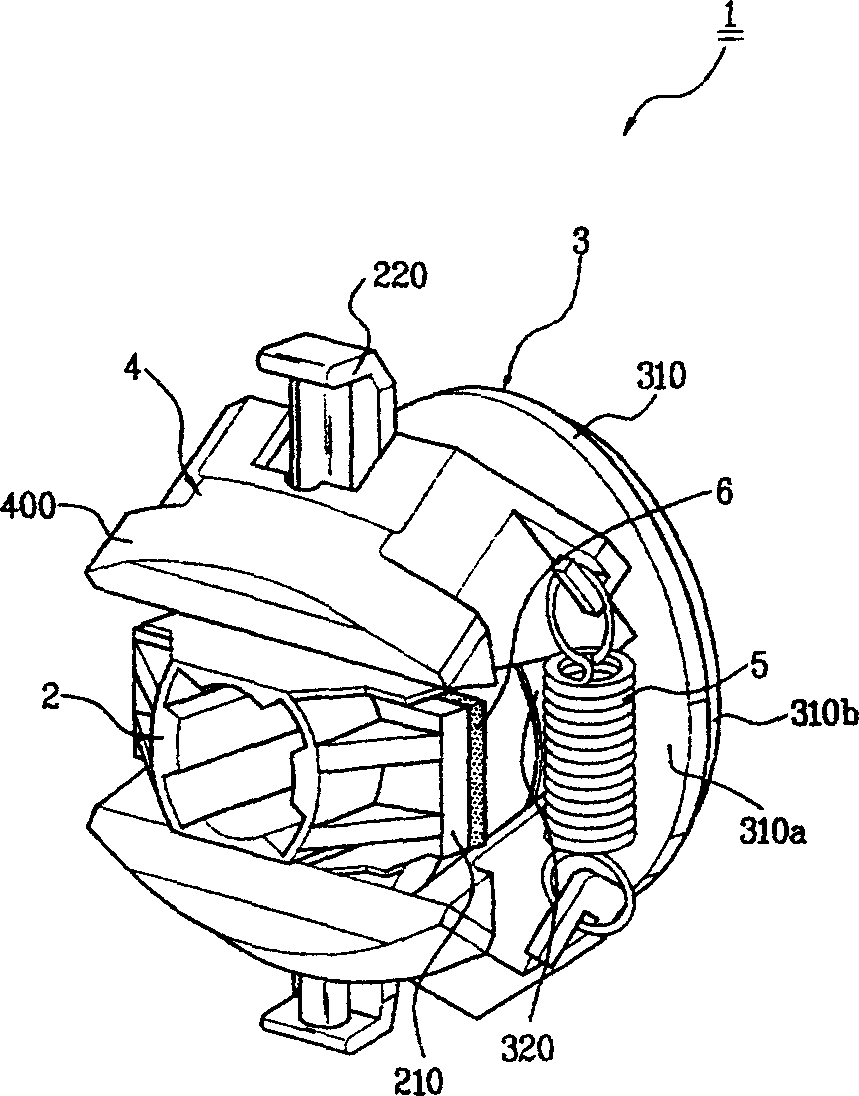
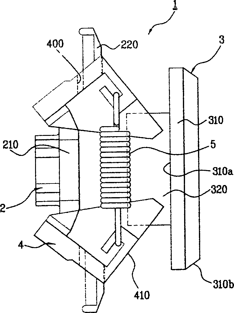
[0031] Such as image 3 , Figure 4a and Figure 4b As shown, the centrifugal switch designed by the present invention includes: the crankshaft 7 of the motor passes through, and a flange 210 is arranged on one side end, and the two sides in the direction that the flange 210 is perpendicular to the crankshaft of the motor Cylinder type hollow shaft 2 extending to form guide arm 220; Equipped with inserting behind flange 210 of hollow shaft 2, shaft mechanism 320 moving along the axis direction of hollow shaft 2 and along the radius at the rear end of shaft mechanism 320 The sliding block 3 of the bushing 310 formed by extending in the direction; while forming the through ...


PUM


Abstract

The invention discloses a structure of centrifugal switch, including: a cylinder type hollow shaft with a motor shaft through, arranged with a flange and formed with guide arms; a shaft mechanism inserted in the back of the flange of the hollow shaft and moving in the axial direction of the hollow shaft and a slide block situated at the back end of the shaft mechanism and forming a shaft lining in the radial direction; the centrifugal brakes with the guide arms passing through the through hole, arranged the left and right sides of the shaft mechanism of the slide block in a hinging mode at the same time and able to turn, and opened under the action of centrifugal force; an extension spring linking two-side centrifugal brakes, making them approach to each other as they are not acted by the centrifugal force and providing return force; a buffer pad provided on the contact surface between the slide block and hollow shaft or on the shaft lining of the slide block. It uses the buffer pad to effectively reduce the produced noise as the brakes act and improve the reliance of the products.

Description

technical field [0001] The invention relates to a centrifugal switch, in particular to a centrifugal switch which reduces the contact noise generated when a switch on a motor in a household electric appliance operates. Background technique [0002] Usually, centrifugal switches are used in electric motors of home appliances such as clothes dryers, such as figure 1 As shown, the electric motor 8 comprises a stator assembly 8b equipped with a main winding wire 9 and an auxiliary winding wire 10 (or starting winding wire). The shaft 7 of the motor of the rotor 8a can rotate inside the stator assembly 8b. [0003] Such as Figure 2a and Figure 2b As shown, a centrifugal force on-off switch, that is, a centrifugal switch 1, is provided on the crankshaft 7 of the motor. [0004] Centrifugal force switch 1 is closed when the motor rotates at a low speed, but as the speed increases, when it reaches 70% to 80% of the synchronous speed, the circuit is disconnected. That is, alth...

Claims


Application Information

Patent Timeline
Patent Type & Authority Applications(China)
IPC IPC(8): H01H35/10
Inventor 方宗哲金相斗
Owner LG ELECTRONICS (TIANJIN) APPLIANCES CO LTD
Why Eureka
Try Eureka