Pneumatic flexible ball-joint

A ball joint and flexible technology, applied in the field of ball joints, can solve the problems of affecting the implementation effect, large space size, complex structure, etc., and achieve the effects of large implementation value, simple control, and flexible movement.

Inactive Publication Date: 2005-01-26
ZHEJIANG UNIV OF TECH
View PDF0 Cites 7 Cited by
  • Summary
  • Abstract
  • Description
  • Claims
  • Application Information

AI Technical Summary

Problems solved by technology

Before the present invention was made, the traditional design idea was based on a purely mechanical structure, and its main disadvantages were the need for an external transmission mechanism, a motor or hydraulic drive, large space size, complex structure, and difficult control, which affected the implementation effect.

Method used


Image

  • Pneumatic flexible ball-joint
  • Pneumatic flexible ball-joint

Examples


Embodiment Construction

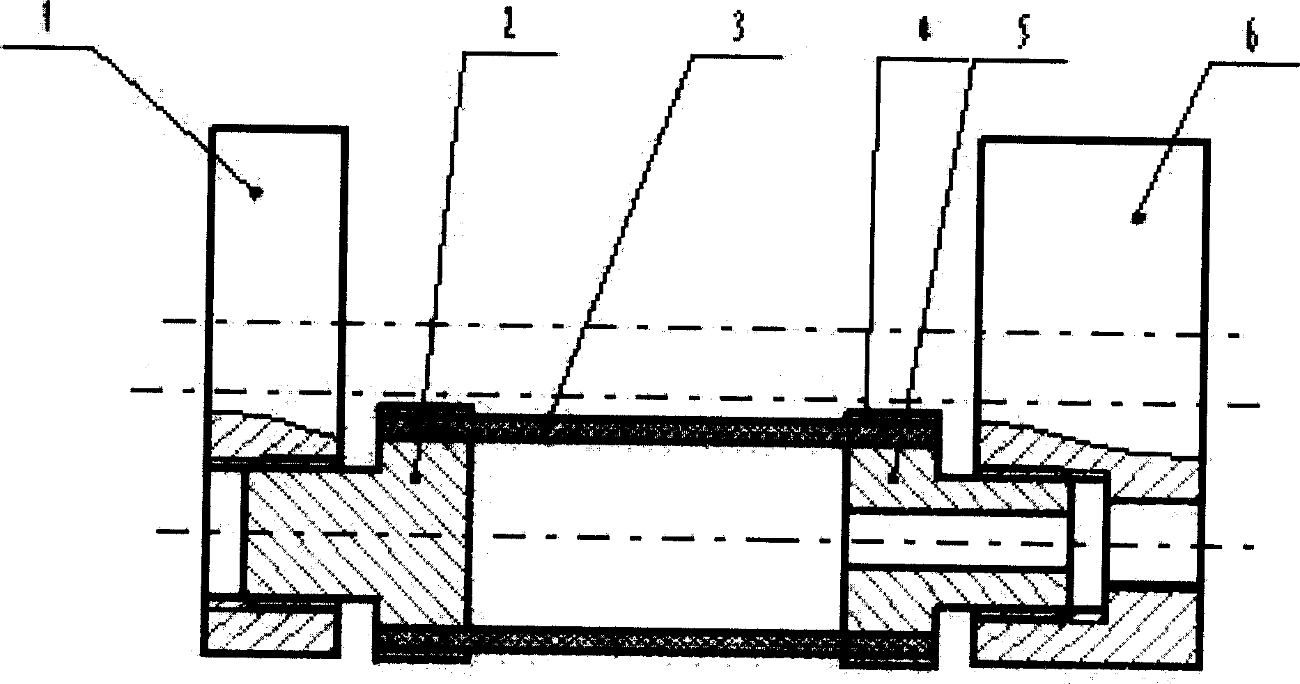
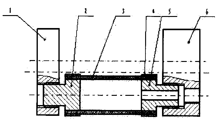
[0008] figure 1 is an example of the present invention. Such as figure 1 As shown, the embodiment of the present invention is: a pneumatic flexible ball joint, which is characterized by a left cover 1, a left seal head 2, a rubber tube 3, a fastening ring 4, a right seal head 5, and a right cover 6. Three threaded holes are arranged at intervals of 120 degrees on the left cover 2, and three stepped holes are arranged at intervals of 120 degrees on the right cover 6, and the large holes of the stepped holes are threaded holes, and the left and right ends of the three same rubber tubes 3 Connect with the left and right sealing heads and the right sealing head 5 respectively to ensure the tightness of the connection between the rubber tube 3 and the left and right sealing heads and the right sealing head 5. The left and right sealing heads are connected to the left cover 1 through ribs, and the fastening ring 4 is tightly sleeved. Outside the rubber tube 3, and located at one e...


PUM


Abstract

The air operated flexibility universal spheric joint, its characteristic is by seals covers (1), seals the attachment (2), the rubber pipe (3), the tight circle (4), seals the attachment (5), seals covers (6) to compose, in seals covers (2) on to be separated 120 to be equipped with three threaded hole, in seals covers (6) on to be separated 120 to be equipped with three stairs holes, also stair hole pocket for threaded hole, three same rubber pipes (3) the about beginnings and ends separately with seal the attachment (2) and seal the connection (5) to connect, Seals the attachment (2) to seal through the thread covers (1) to connect, the tight circle (4) the tight wrap in the rubber pipe (3) outside, seals the attachment (5) to cover (6) through spiral Wen Yufeng to connect, is sealing the attachment (5) the center to suppose to pass the hole, causes the rubber pipe (3) the cavity and the atmosphere is interlinked. Its structure simple reasonable, movement nimble, control simple, the use effect is good, has the bigger implementation value.

Description

technical field [0001] The invention belongs to a ball joint, in particular to a pneumatic flexible ball joint, which is suitable for designing and manufacturing mechanical fingers. Background technique [0002] The design of the joint is a key technology in the design and manufacture of the mechanical finger. The sensitivity of the joint and the complexity of the joint structure directly determine the structure and size of the mechanical finger. Before the present invention was made, the traditional design idea was based on a purely mechanical structure. Its main disadvantages were the need for an external transmission mechanism, motor or hydraulic drive, large space size, complex structure, and difficult control, which affected the implementation effect. Contents of the invention [0003] The invention overcomes the shortcomings of the traditional method and the prior art, and provides a pneumatic flexible ball joint with simple and reasonable structure, flexible movemen...

Claims


Application Information

Patent Timeline
Patent Type & Authority Applications(China)
IPC IPC(8): B25J1/02F15B15/08
Inventor 张立彬杨庆华鲍官军阮健
Owner ZHEJIANG UNIV OF TECH
Why Eureka
Try Eureka