Passive non-contacting smart bearing suspension for turbo blood-pumps

A technology of blood pumps and bearings, applied in the direction of blood pumps, pumps, pump devices, etc., can solve the problems that simplicity and reliability are not the ultimate

Inactive Publication Date: 2005-02-02
迈克尔.P.戈尔多夫斯基
View PDF1 Cites 18 Cited by
  • Summary
  • Abstract
  • Description
  • Claims
  • Application Information

AI Technical Summary

Problems solved by technology

[0004] The disadvantage of third-generation pumps is the need for an electronic control system to stabilize the magnetic bearings
A fully magnetically levita

Method used


Image

  • Passive non-contacting smart bearing suspension for turbo blood-pumps
  • Passive non-contacting smart bearing suspension for turbo blood-pumps
  • Passive non-contacting smart bearing suspension for turbo blood-pumps

Examples


Embodiment Construction

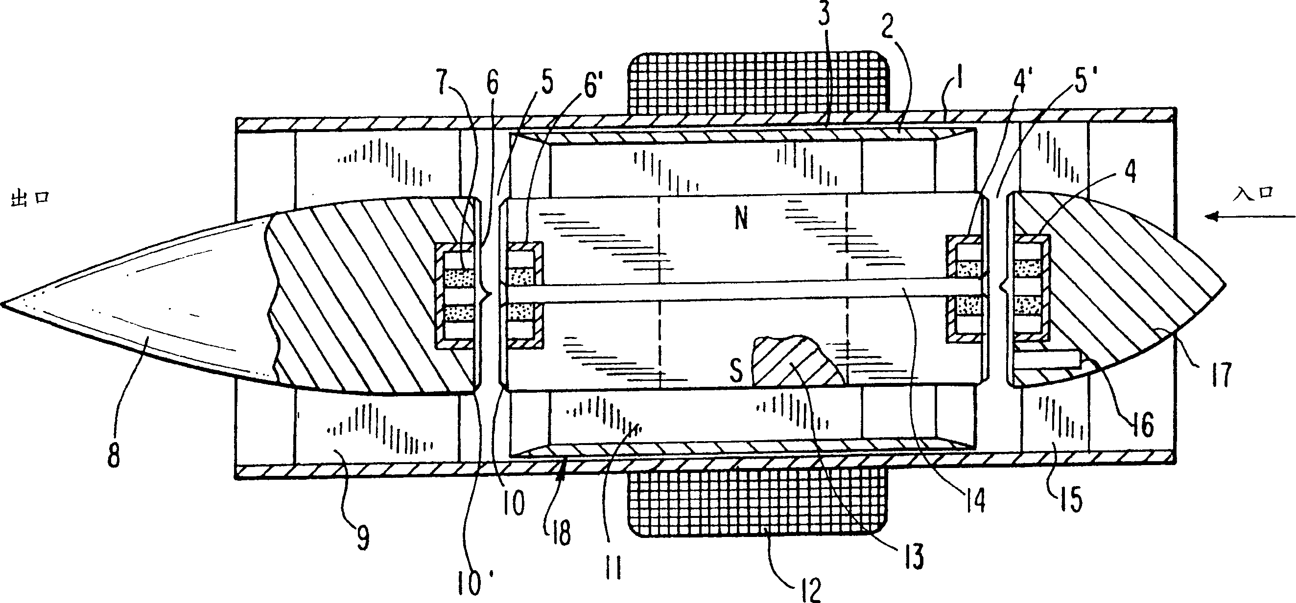
[0025]To better describe the main elements of the invention, figure 1 Only the main components of the axial flow booster pump are shown in the figure. An axial pump is shown in the figure, but this is not meant to be limiting. The same bearing suspension can also be applied to centrifugal booster pumps. This is illustrated in the Goldowsky patent cited above.

[0026] The rotor of the pump is generally depicted as item 18 . It includes helical impeller blades 11, circular bearing parts 2, magnet thrust bearings at each end, parts 4 and 4', thin windows 10 and 10', brushless motor armature magnet parts 13, and blood flow guide Hole 14, the pilot hole 14 is used to flush the rotor gap at each end. The concept of using a central shaft hole in the rotor to achieve interstitial flushing flow is covered by Goldowsky, US Patent No. 6,716,157, entitled "Improved Magnetic Levitation Blood Pump," issued April 6, 2004. The magnet assembly is hermetically sealed by a thin (typically ...


PUM


Abstract

The ultimate in suplicity and reliability, an axial-flow blood pump is supported by an all passive contact-free hybrid bearing suspension that can measure differential pump pressure. The preferred suspension consists of a radial hydrodynamic journal bearing with axial magnetic thrust bearings. The thrust bearing consists of repulsion magnet pairs positioned at each end of the rotor. This holds bidirectional loads with a stable restoring force (negative axial stiffness). Rotor axial position shifts with load and is monitored with a position sensor to inherently provide pump differential pressure (which may be used to physiologically control pump flow rate). The hydrodynamic radial and 'smart' axial magnet thrust bearings use large gaps to eliminate hemolysis and are actively washed out under pressure with fresh blood to eliminate thrombosis.

Description

technical field [0001] The present invention relates to an axial flow or centrifugal booster blood pump, and more particularly to such a blood pump in which the rotor is passively suspended, for measuring differential pressure in a left ventricular assist device (LVAD). Background technique [0002] The first generation of blood pumps used and still use a flexible pumping chamber in contact with the blood. They do not have blood-soaked bearings and are not prone to thrombosis. The advantage is their inherent pulsating flow. In competing for use as a LVAD (left ventricular assist device), they have the disadvantage of being oversized. Newer second-generation booster pumps have high-speed impellers, like the Jarvik 2000 and Micromed axial pumps. They are much smaller, but have contact bearings that suspend the rigid motor. Most second-generation pumps are the larger centrifugal type. In axial flow and centrifugal booster pumps, bearing contact can cause undesired blood cl...

Claims


Application Information

Patent Timeline
IPC IPC(8): A61M1/10F04D13/06F04D7/00
CPCA61M2001/1017A61M1/101A61M2001/1015A61M60/824A61M60/422A61M60/148A61M60/816A61M60/232A61M60/237A61M60/178A61M60/822
Inventor 迈克尔·P·戈尔多夫斯基
Owner 迈克尔.P.戈尔多夫斯基
Why Eureka
Try Eureka