Coated sheet cutting method and apparatus

A thin film and coating technology, which is applied in metal processing and other directions, can solve the problems of cracks in the coating layer, difficult cutting conditions, cracks, etc., and achieve the effects of preventing cracks and cracks, reducing the amount of bending, and reducing local deformation

Active Publication Date: 2005-02-02
FUJIFILM CORP
View PDF0 Cites 8 Cited by
  • Summary
  • Abstract
  • Description
  • Claims
  • Application Information

AI Technical Summary

Problems solved by technology

[0003] However, since various materials are used for manufacturing coated sheets in different ways according to requirements, it becomes more difficult to select suitable cutting conditions to shear along the feed direction when pulling out coated sheets rolled into a roll form coated flakes
If cutting conditions are not properly selected, cracks and / or fissures may result in the coating near the cut edge of the sheet
Especially, when the coating layer is hard and brittle, the above-mentioned cracks and / or fissures may be significantly formed in the coating layer

Method used


Image

  • Coated sheet cutting method and apparatus
  • Coated sheet cutting method and apparatus
  • Coated sheet cutting method and apparatus

Examples


Embodiment Construction

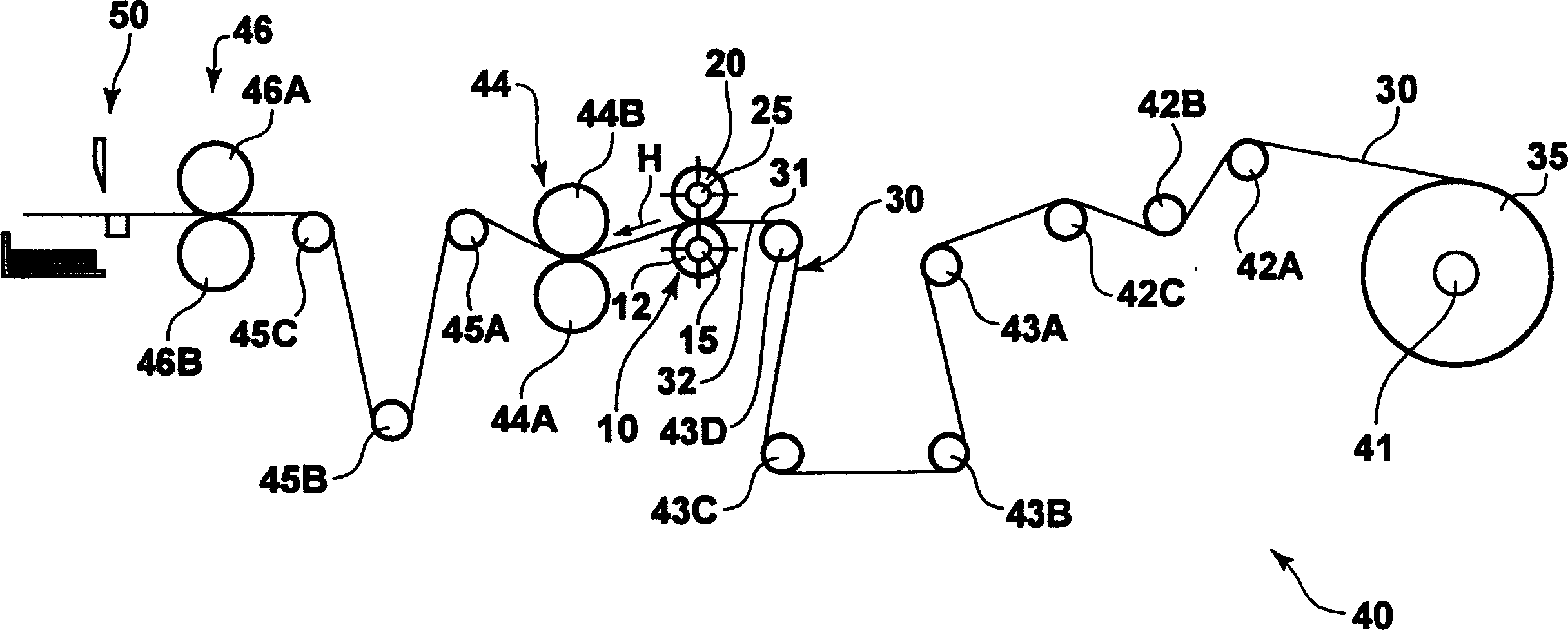
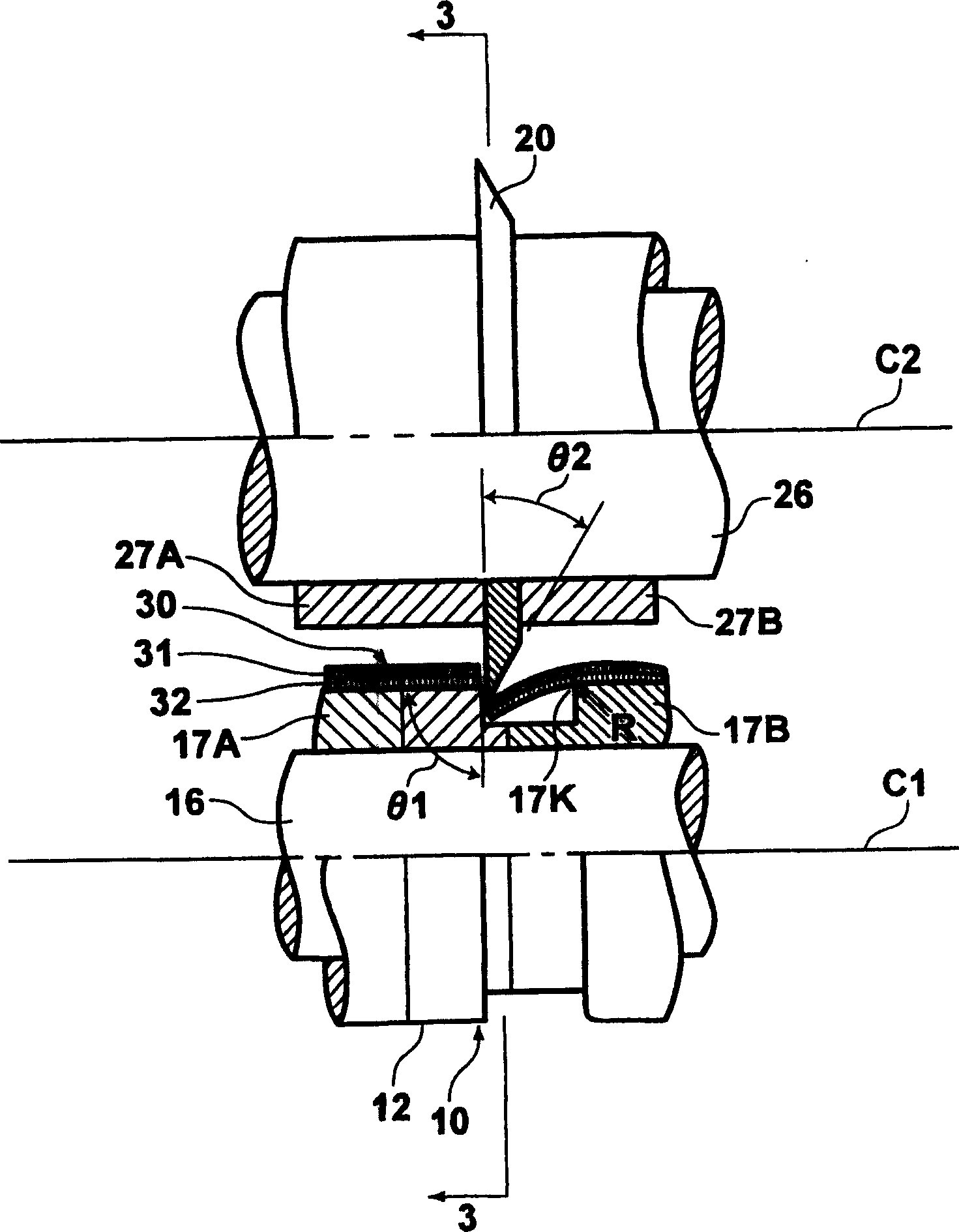
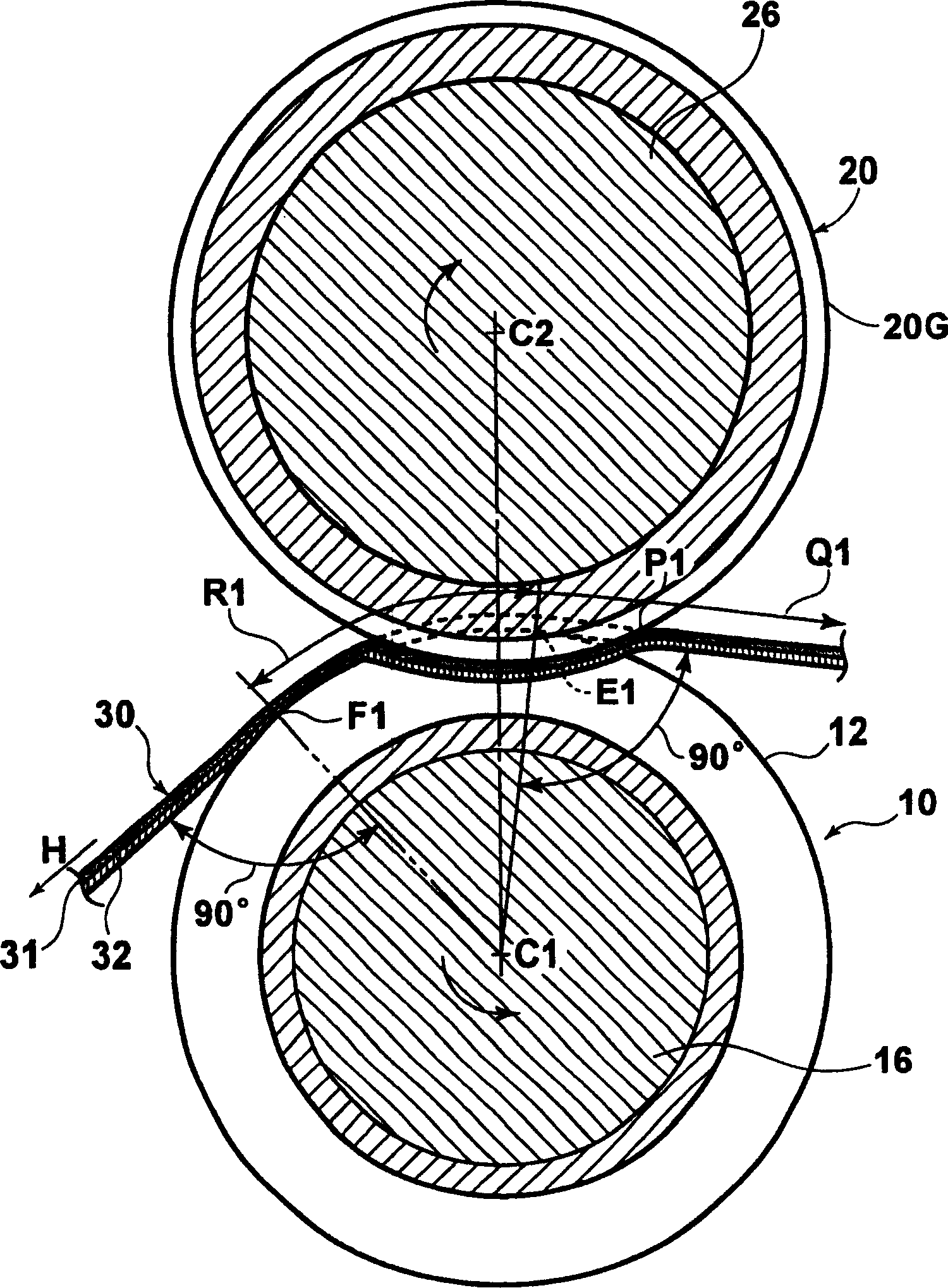
[0027] Hereinafter, a first embodiment of the present invention will be described in detail with reference to the accompanying drawings. figure 1 is a side view showing a schematic structure of a coating sheet cutting device for implementing a coating sheet cutting method according to an embodiment of the present invention; figure 2 yes figure 1 An enlarged partial cross-sectional view of the coating flake cutting device of , showing the positional relationship between the lower cutting blade, the upper cutting blade, and the coating flake; and image 3 is along figure 2Schematic cross-section taken at line 3-3.

[0028] The shown coating flake cutting device comprises a disc-shaped lower cutting blade 10, a lower blade rotating motor 15 for rotating the lower cutting blade 10, a disc-shaped upper cutting blade 20 arranged opposite to the lower cutting blade 10, and a disc-shaped upper cutting blade 20 for rotating the upper cutting blade 10. The upper blade turning motor...


PUM


Abstract

The disc-shaped lower cutting blade and the disc-shaped upper cutting blade having a sharper corner than that of the lower cutting blade are arranged such that their rotational axes are parallel to each other, and a part of these blades overlap each other along the direction in which the rotational axis extends. As the upper and lower cutting blades are rotated, the coating flakes with the coating layer on one side are fed through between the upper and lower cutting blades in a direction perpendicular to these axes of rotation so that they are positioned opposite the coating layer. The coated flake surface on one side remains in circumferential contact with the lower cutting blade. When the coated flake is sheared, the contact start position where the contact between the coated flake and the upper cutting blade starts is set upstream in the feeding direction of the coated flake but at the position where the coated flake is in circumferential contact with the lower cutting blade outside of the contact area.

Description

technical field [0001] The present invention relates to methods and apparatus for cutting coated flakes. In particular, the present invention relates to a method and apparatus for cutting a coated flake by passing it between opposing disc-shaped cutting blades. Background technique [0002] Conventionally, there is known a coated sheet comprising a sheet substrate such as paper, film, or resin-coated paper, and a coating layer formed on the sheet substrate, wherein the coating layer is filled with Fine particles of silicon or similar held together. Such coated flakes are formed into rolls by applying a liquid coating to a long substrate, drying the coated substrate, and rolling the dried substrate into roll form. The roll thus obtained is cut, when unrolled from the rolled roll, by cutting the roll in the roll feed direction and / or by cutting the roll in the cross-roll direction, i.e. perpendicular to the roll feed direction to the desired size. Thereafter, these cut she...

Claims


Application Information

Patent Timeline
Patent Type & Authority Applications(China)
IPC IPC(8): B26D1/24B26D7/26
CPCB26D2001/0053B26D1/245B26D7/2635Y10T83/04Y10T83/7813Y10T83/783Y10T83/9403
Inventor 川井弘一
Owner FUJIFILM CORP
Why Eureka
Try Eureka