Magnetic tape cartridge

A chuck and tape technology, used in magazine/cassette storage, magazine/cassette manufacturing equipment, data recording, etc., which can solve the problem of unstable positioning, flatness of the reference surface, reduced surface accuracy, and inability to ensure positioning accuracy. and other problems, to achieve stable positioning accuracy, ensure flatness and surface accuracy, and maintain a good height position.

Inactive Publication Date: 2005-02-02
FUJIFILM CORP
View PDF0 Cites 0 Cited by
  • Summary
  • Abstract
  • Description
  • Claims
  • Application Information

AI Technical Summary

Problems solved by technology

[0005] Then, on such a chuck housing, in order to improve the release property during molding as mentioned above, a film-drawing slope is provided on the side wall surface, and a film-drawing slope is also formed on the contact surface of the positioning part, and the positioning member When the contact position of the contact position changes in the up and down direction, corresponding to the above-mentioned film pulling slope, the positioning position changes, and there is a problem of unstable positioning.
[0006] In addition, when "shrinkage cavity" during molding occurs on the reference surface of the bottom surface of the chuck housing, the flatness and surface accuracy of the reference surface will be reduced, and positioning accuracy cannot be ensured.

Method used


Image

  • Magnetic tape cartridge
  • Magnetic tape cartridge
  • Magnetic tape cartridge

Examples


Embodiment

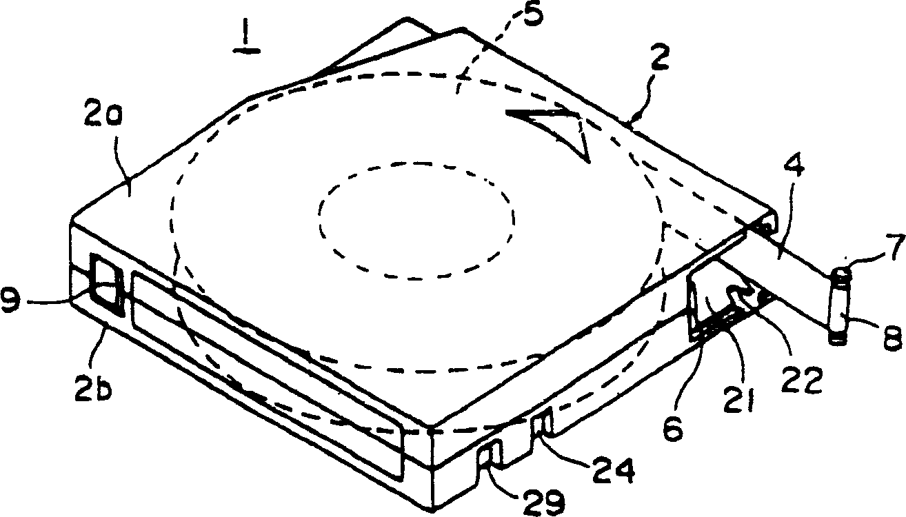
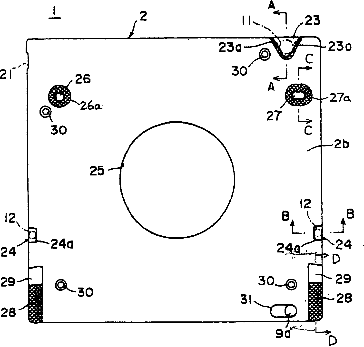
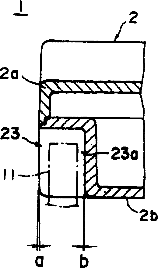
[0025] The embodiments of the present invention will be described in detail below with reference to the drawings. figure 1 Is a perspective view of the tape cartridge of the embodiment in which the tape is pulled out, figure 2 Is the bottom view of the chuck housing, Figure 3 ~ Figure 6 Yes figure 2 A-A~D-D section view. The front, rear, left, and right directions in the following description correspond to the tape cartridge loading direction ( figure 1 Oblique upper right direction) marked.

[0026] The tape chuck 1 is rotatably accommodated in a substantially rectangular flat chuck housing 2 formed by connecting the upper housing 2a and the lower housing 2b by screws or the like, and a single reel 5 is wound on the reel with a pull-out pin fixed at the end. (Pull out member) of the tape 4. An opening 21 for pulling out the magnetic tape 4 is formed on one side wall (right side wall) of the chuck housing 2. The opening 21 passes through a sliding door 6 energized in the closi...


PUM


Abstract

The invention relates to a tape chuck, which is characterized in that a single reel of the roll-package tape is rotatably accommodated in a chuck housing; wherein, a base level, contacting with the locating member of a recording and replaying device, is positioned on the bottom surface of the chuck housing; the bottom panel of the housing of the part forming the base level has even thickness with flanges and steps; in addition, the bottom panel of the housing is thinner than a lower housing.

Description

Technical field [0001] The present invention relates to a magnetic tape chuck with a single reel for rotatably accommodating a tape in a chuck housing, and particularly to a structure for positioning the housing. Background technique [0002] In a tape cartridge traditionally used as a recording medium on an external storage device such as a computer, a tape is wound on a single reel, and the reel is rotatably housed in the chuck housing. Since the tape is used as a computer to save data and store important information, its structure should not cause malfunctions such as tape jams, and the tape cannot be pulled out if you are not careful. [0003] In addition, when the above-mentioned tape cartridge is installed in a recording and reproducing apparatus, it is required to be positioned correctly. For example, a positioning portion is formed on the side surface of the chuck housing, and a positioning member of the recording and reproducing device is contacted on the contact wall su...

Claims


Application Information

Patent Timeline
IPC IPC(8): G11B23/107G11B23/113
CPCG11B23/113G11B23/107
Inventor 高桥大助志贺英昭森田清夫石原祐辅
Owner FUJIFILM CORP
Why Eureka
Try Eureka