Differential signal receiving device and differential signal transmission system

A technology of differential signal and receiving equipment, applied in the field of differential signal receiving equipment and differential signal transmission system

Inactive Publication Date: 2005-02-02
RENESAS ELECTRONICS CORP
View PDF1 Cites 15 Cited by
  • Summary
  • Abstract
  • Description
  • Claims
  • Application Information

AI Technical Summary

Problems solved by technology

[0008] However, when the existing signal transmission system transmits the third differential signal instead of the normal-phase single-ended signal and the reverse-phase single-ended signal, the third differential signal will be reflected annoyingly when reaching the terminal of the signal line

Method used


Image

  • Differential signal receiving device and differential signal transmission system
  • Differential signal receiving device and differential signal transmission system
  • Differential signal receiving device and differential signal transmission system

Examples


Embodiment Construction

[0027] Specific embodiments of the present invention will be explained below with reference to the drawings.

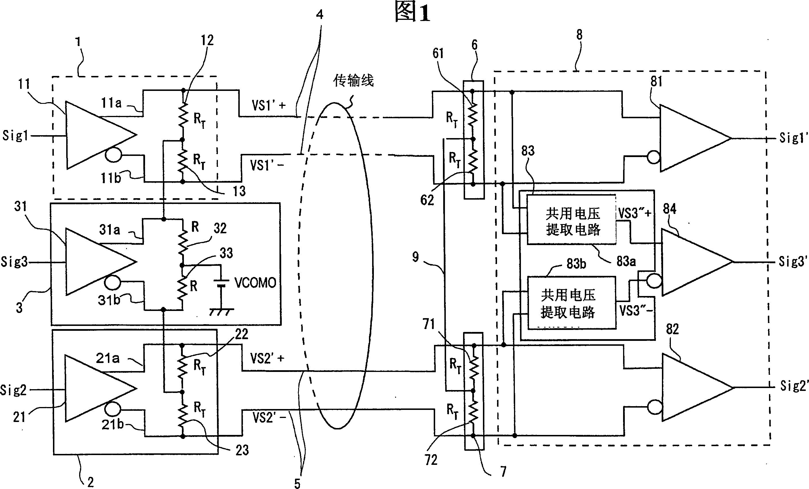
[0028] Firstly, please refer to FIG. 1 , which shows a circuit block diagram of a differential signal transmission system according to a specific embodiment of the present invention.

[0029] The differential signal transmission system shown in Figure 1 includes a first output buffer 1, a second output buffer 2, a third output buffer 3, a signal line pair 4, a signal line pair 5, a first terminal 6, a second terminal 7 and an input buffer 8.

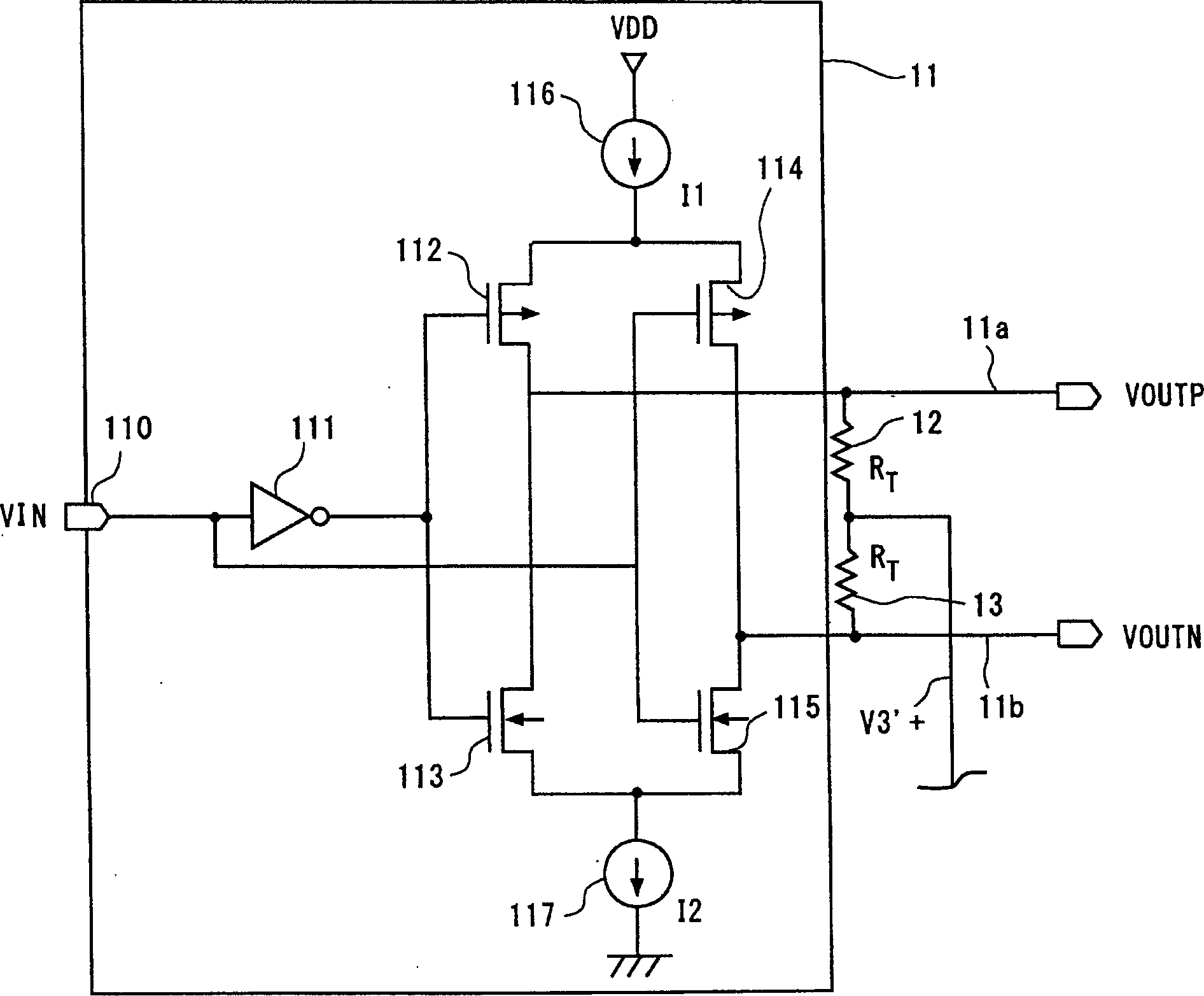
[0030] The first output buffer 1 is an example of a first transmission circuit, which includes a differential signal output circuit 11 and resistors 12 , 13 .

[0031] The differential signal output circuit 11 outputs the first differential signal (VS1+ and VS1-) to the signal line pair 4 through the output line pair 11a and 11b of the differential signal output circuit 11, corresponding to the input signal Sig1. Specifically,...


PUM


Abstract

The intermediate node of the first terminator connected between a pair of signal lines transmitting the first differential signal with one side of the third differential signal as a common voltage and the intermediate node of the second terminator connected between a pair of signal lines transmitting the second differential signal with the other side of the third differential signal as a common voltage are connected by the intermediate connection. Thus, the intermediate node of the first terminator and the intermediate node of the second terminator act as a virtual ground of the third differential signal, enabling the matching of the impedance of the terminators related to the third differential signal and the impedance of the signal lines related to the third differential signal. It is thus able to prevent the reflection of the third differential signal.

Description

technical field [0001] The present invention relates to a differential signal receiving device and a differential signal transmission system, more specifically, to a differential signal receiving device and a differential signal transmission system utilizing a plurality of differential signals. Background technique [0002] Signal transmission devices that transmit differential signals through transmission line pairs have been used. Transmitting differential signals through transmission line pairs is effective in reducing noise because it can cancel noise by using signals with substantially the same amplitude and phase that appear simultaneously on transmission line pairs, and suppress electromagnetic interference (EMI: used for external communication Generic term for devices making electromagnetic disturbances and interruptions). [0003] Japanese Unexamined Patent Application 2002-204272 in figure 2 is described and shown in a signal transmission system that superimposes...

Claims


Application Information

Patent Timeline
Patent Type & Authority Applications(China)
IPC IPC(8): G06F3/00H03K5/003H03K5/22H04L5/20H04L25/02H04L25/08
CPCH03K5/003H04L5/20H04L25/0278H04L25/0272
Inventor 堀良彦
Owner RENESAS ELECTRONICS CORP
Why Eureka
Try Eureka