
Drive recorder

A camcorder, video camera technology, applied in pedestrian/occupant safety arrangement, registration/indication of vehicle operation, television and other directions, can solve problems such as images in specific directions or images of specific objects as the cause, and achieve reliable recording , the effect of simple operation

Inactive Publication Date: 2005-02-02
PANASONIC CORP
View PDF1 Cites 14 Cited by
  • Summary
  • Abstract
  • Description
  • Claims
  • Application Information

AI Technical Summary

Problems solved by technology

[0003] However, in the above-mentioned conventional driving video cameras for vehicles, the position of the camera that captures the surrounding environment of the vehicle is fixed, and usually mainly captures the situation ahead when the vehicle is running. Therefore, it is not always possible to capture an image in a specific direction that is the cause of an accident. Or the image of a specific object, whether the scene is photographed is accidental

Method used


Image

  • Drive recorder
  • Drive recorder
  • Drive recorder

Examples


Embodiment 1

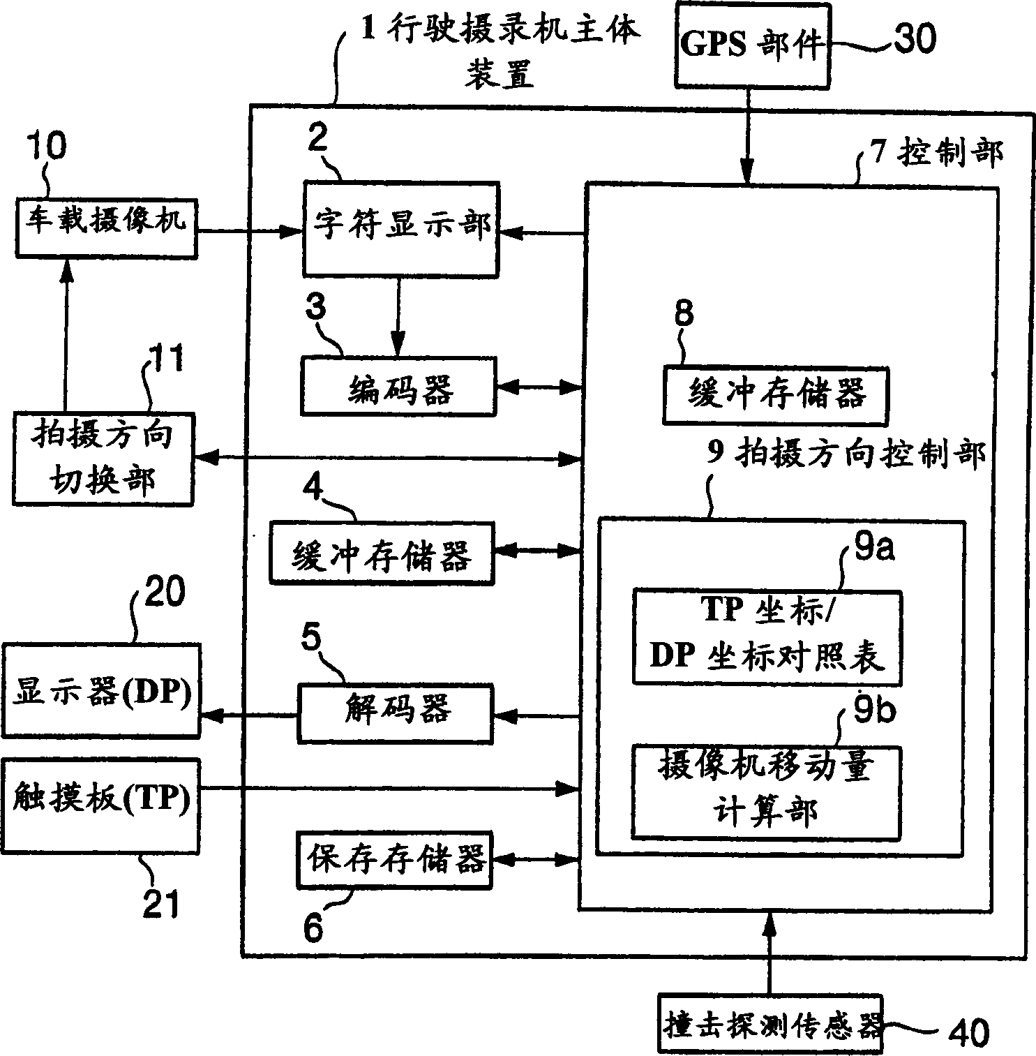
[0029] figure 1 The structure of the driving video camera for a vehicle according to the first embodiment of the present invention is shown. Such as figure 1 As shown, the driving video camera is provided with: as a peripheral device connected to the main body device 1 of the driving video camera, a vehicle-mounted camera 10 that adopts a CCD for shooting the surrounding scenery outside the vehicle and the situation in the vehicle, and the position of the vehicle-mounted camera 10 is switched. The shooting direction switching part 11 of the shooting direction displays the image of the surrounding scenery or situation taken by the vehicle camera 10 on the display (DP) 20 on the screen, and the one that is arranged in front of the screen of the display 20 and outputs the coordinate data of the pressed position The touch panel (TP) 21, the GPS unit 30 for detecting the current position of the host vehicle using GPS (Global Positioning System), and the impact detection sensor 40 ...

Embodiment 2

[0040] Next, refer to Figure 12 to Figure 14 Example 2 of the present invention will be described. The driving video camera of the present embodiment 2 is the same as that of the embodiment 1. figure 1 and Figure 11 The difference of the shown structure is: there is also a communication unit 100 for sending data to an external organization such as an information center, a screen grabber 101 for obtaining an image of the display screen by the control unit 7B, and an on-board camera 10 that can be operated on the screen. The shooting direction control section 9B for changing the shooting magnification. And, in the present embodiment 2, vehicle-mounted video camera 10 adopts the structure that its shooting magnification is variable, as Figure 13 As shown, the shooting magnification can also be changed through screen operations on the display screen 110 . For this reason, a send button 114 is displayed on the display screen 110 in addition to the S button 11 , the M button ...


PUM


Abstract

A drive recorder attains scenic images surrounding a vehicle or images inside a vehicle chamber in a specific direction, as being useful for verifying a cause of an accident. As an impact sensor detects an occurrence of an accident, a control unit displays an image by an on-vehicle camera on a screen of a display. Accordingly, a user is able to quickly record target objects that supposedly help to verify the cause of the accident, such as the vehicle running into from behind and running away, a traffic light, a traffic marking and so forth, by simply turning a photographic direction of the on-vehicle camera toward the target objects, with a simple operation on a touch panel, even in an emergency.

Description

technical field [0001] The present invention relates to a drive recorder for recording the driving state of a vehicle, in particular to a drive recorder capable of recording situations such as accidents by recording the surrounding environment of the vehicle. Background technique [0002] The traditional vehicle driving camera is a device used to trace the cause of the accident in the event of personal injury, vehicle damage, etc., using vehicle sensor signals such as vehicle speed / acceleration / brake pressure / steering wheel angle before and after the accident to analyze the driving status of the vehicle and find out the cause of the accident. In addition, a device has been proposed that installs a camera that captures the surrounding environment of the vehicle, and records the images captured by the camera to clarify the situation when the accident occurred. Such a conventional driving video camera for a vehicle includes, for example, a device disclosed in Japanese Patent A...

Claims


Application Information

Patent Timeline
Patent Type & Authority Applications(China)
IPC IPC(8): B60R21/00B60R1/00B60R11/02B60R11/04B62D41/00G07C5/08
CPCG07C5/085
Inventor 山口健
Owner PANASONIC CORP
Learn More