Working table device for table type applicator

A coating machine and workbench technology, which is applied in the direction of surface coating liquid devices, coatings, manufacturing tools, etc., can solve the problems of increasing installation space, increasing transportation costs, and increasing width dimensions

Inactive Publication Date: 2005-02-09
SUMITOMO HEAVY IND LTD
View PDF1 Cites 4 Cited by
  • Summary
  • Abstract
  • Description
  • Claims
  • Application Information

AI Technical Summary

Problems solved by technology

If the slider part vibrates, the acceleration adjustment time T (distance) will become longer, so the part where the coating is uneven (the discarded part of the film-forming substrate) will be longer
[0021] However, if the center of gravity is lowered in order to solve this problem, fo

Method used


Image

  • Working table device for table type applicator
  • Working table device for table type applicator
  • Working table device for table type applicator

Examples


Embodiment Construction

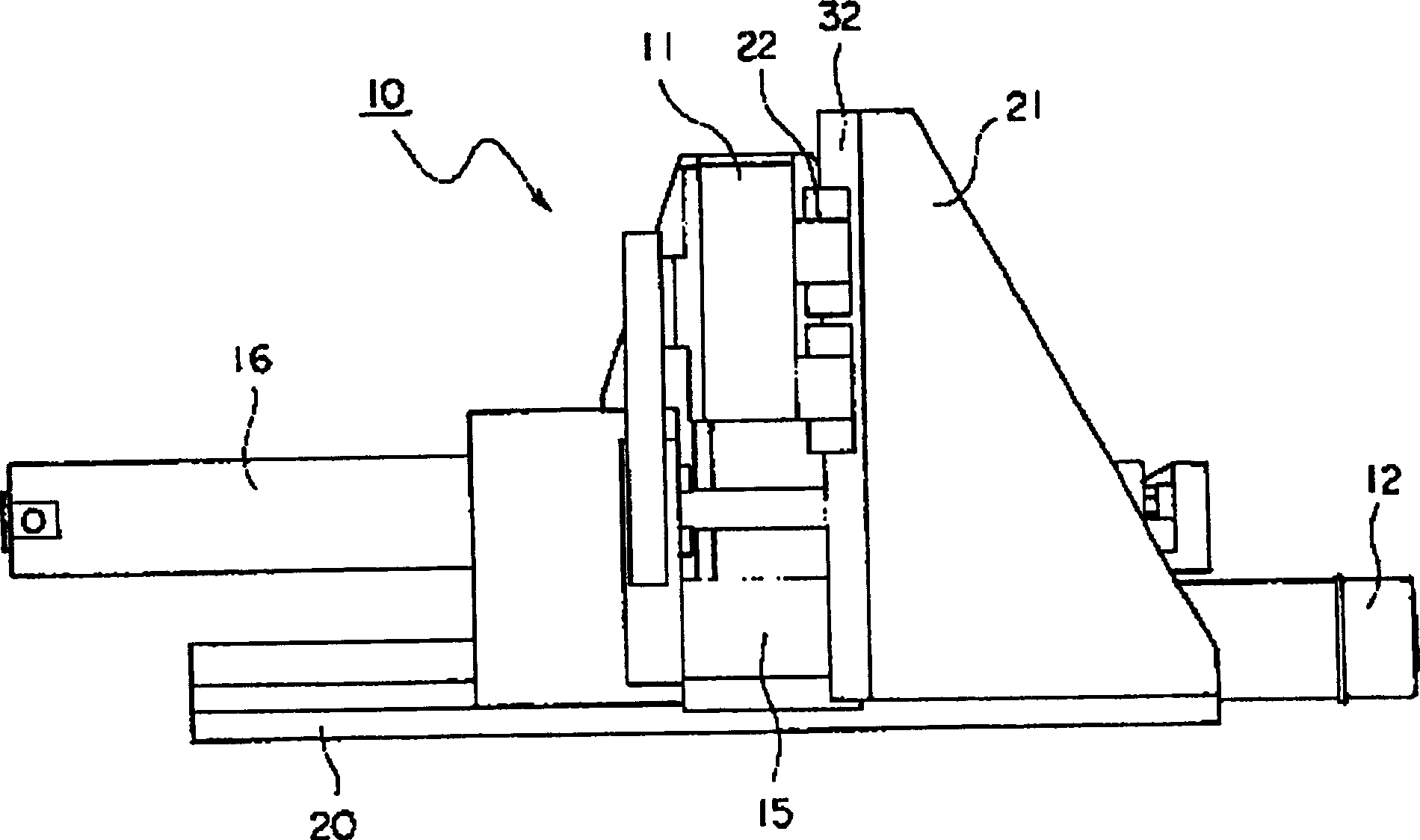
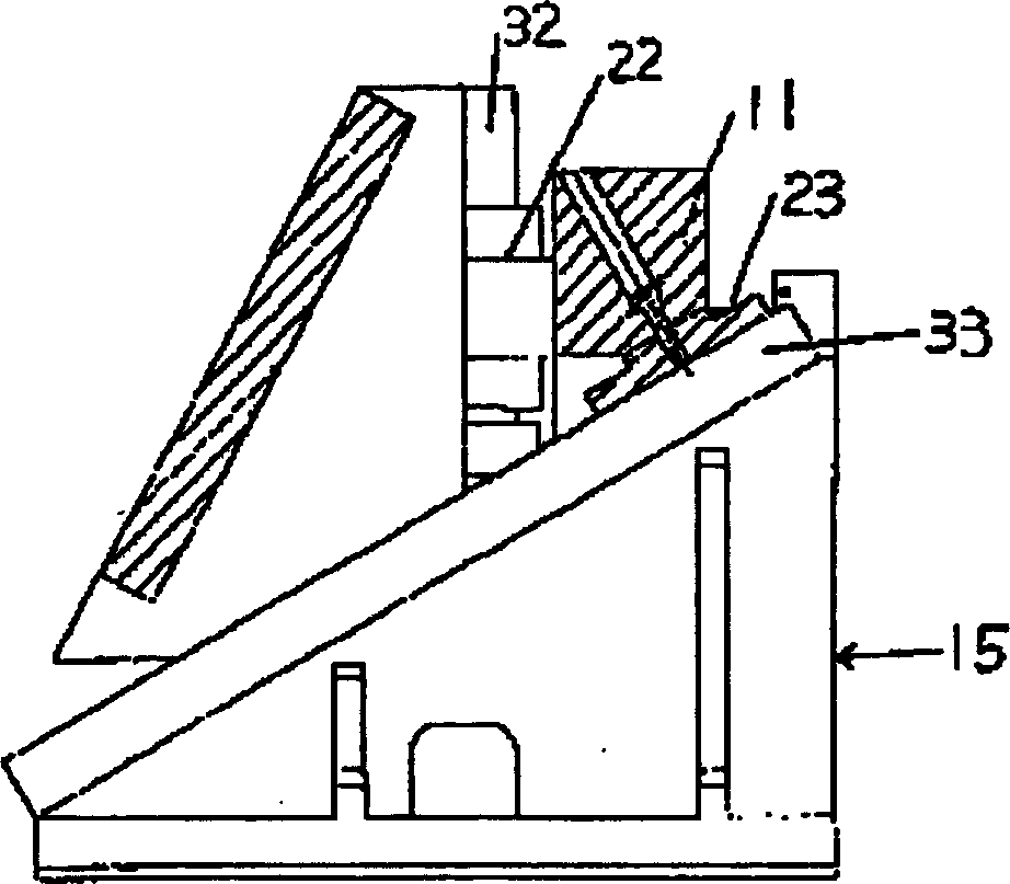
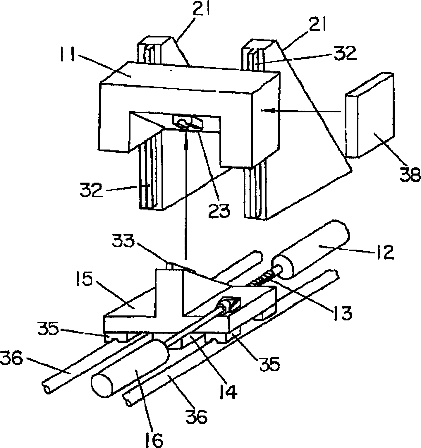
[0039] Refer below Figure 1 ~ Figure 3Embodiments of the table device for a table-top coater according to the present invention will be described. The workbench device of the present invention is characterized in that it improves the Figure 7 Illuminated Z-axis drive mechanism. Thus, in Figure 1 ~ Figure 3 Only the Z-axis drive mechanism is shown in the figure, and only the Z-axis drive mechanism will be described below. That is, it can be considered that the structure and function other than the Z-axis drive mechanism Figure 4 , Figure 5 The same as shown and described.

[0040] If used Figure 4 , Figure 5 As described above, two guide rails 110A, 110B extending parallel to each other are provided on both sides of the stone table 160 corresponding to both sides of the substrate table 100, and are arranged so as to be movable along these guide rails 110A, 110B. Y-axis drive mechanisms (first slide mechanisms) 120A, 120B constituted by linear motors.

[0041] In...


PUM


Abstract

Provided is a stage apparatus which prevents the generation of pitching vibration by lowering the center of gravity of a slider part. The stage apparatus for a table coater is equipped with a first slider which can move in the Y-axis direction along the surface of a substrate table 100 on which a substrate to be treated is mounted and a second slider which is combined with the first slider to be able to move in the Y-axis direction with the first slider and drives a nozzle part 140 vertically. The first slider is composed of two Y-axis drive mechanisms 120A and 120B by linear motors which can travel along two rail parts 110A and 110B installed at positions corresponding to both sides of the substrate table to extend in parallel with each other. The second slider is composed of two slide wedge mechanisms 10 combined with the two Y-axis drive mechanisms. The nozzle part is set between the vertically moving blocks 11 in the two slide wedge mechanisms.

Description

technical field [0001] The present invention relates to a workbench device, in particular to a workbench device suitable for a desktop coating machine. Background technique [0002] As an example of a coater, there is a coater which coats a thin film made of a specific material onto a glass substrate, for example, in the process of manufacturing a liquid crystal panel. Hitherto, such coaters mainly employ a spin coater, that is, a so-called spin coater. However, the structure of the spin coater has a problem that almost all of the expensive coating material dripped on the substrate is discarded. [0003] Therefore, in recent years, tabletop coaters have been offered instead of spin coaters. The desktop coater is a machine that slides a nozzle part having a spray port of a coating material of a certain length or a table on which a substrate to be processed is mounted along one axis to perform coating, and has the advantage of reducing the amount of waste of the coating mate...

Claims


Application Information

Patent Timeline
IPC IPC(8): G02F1/13B05C5/00B05C11/00B23Q5/00
CPCB23Q1/44B65G49/061G02F1/13H01L21/68742
Inventor 中森靖仁镒广诚
Owner SUMITOMO HEAVY IND LTD
Why Eureka
Try Eureka