Filter for processing machines, specially extruders

A screening device and extruder technology, applied in separation methods, filtration separation, membrane technology, etc., can solve problems such as difficult to clean, complicated structural manufacturing process, etc., and achieve the effect of expansion compensation

Inactive Publication Date: 2005-02-09
COPERION
View PDF2 Cites 4 Cited by
  • Summary
  • Abstract
  • Description
  • Claims
  • Application Information

AI Technical Summary

Problems solved by technology

This structural solution is structurally and

Method used


Image

  • Filter for processing machines, specially extruders
  • Filter for processing machines, specially extruders
  • Filter for processing machines, specially extruders

Examples


Embodiment Construction

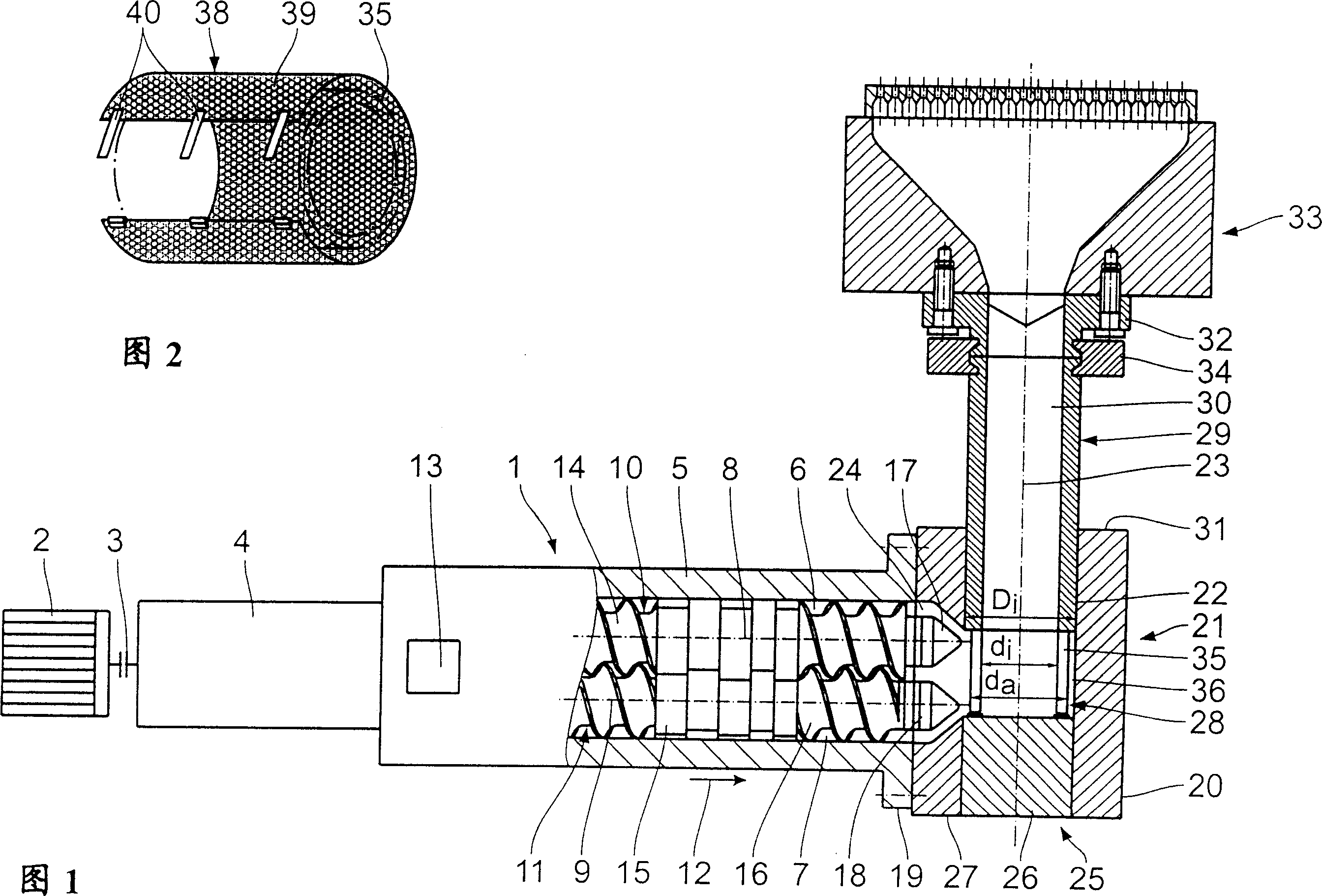
[0015] According to FIG. 1 , an extrusion device for producing, in particular, plastics has an extruder 1 . The extruder is driven by a motor 2 via a coupling 3 and transmission 4 . The extruder 1 has an extruder housing 5, two housing holes 6, 7 with mutually parallel axes 8, 9 are formed in the housing, and the housing holes are distributed parallel to each other and connected to each other to form a roughly "8". ” shape, two worm shafts 10, 11 connected to the transmission device 4 are arranged in the housing holes 6, 7. The worm shafts 10 , 11 are driven in the same direction or in opposite directions, and the extruder 1 has an inlet funnel 13 arranged downstream of the drive 4 in the conveying direction 12 , to which one or more treatment zones are connected. For this purpose, a worm part 14 , a kneading part 15 and again a worm part 16 are attached in sequence on the worm shafts 10 , 11 in the conveying direction. Worm tips 17 , 18 are formed at the rear ends of the wo...


PUM


Abstract

The invention relates to a material preparation machine, which is characterized in that a screening device (21) of an extruder (1) is provided with a casing (20), wherein the casing is provided with an extending through hole (22) which is vertical to the axis (8, 9) of the extruder (1); a screening rod (25) is arranged in the hole, which can be shifted along the axis (23) direction of the hole. A screening section (28) is tightly connected in the screening rod (25), which forms a pipe section (29); the screened material flows out though the pipe section along the direction of axis (23) of the through hole (22).

Description

technical field [0001] The invention relates to a screening device for manufacturing machinery, especially extruders. Background technique [0002] In a screening device known from DE 3419822 A1 (corresponding to US Patent 4597870), the screening rod is made in two parts. In the sieving section, an annular outlet channel opens into an outlet channel extending parallel to the inlet channel. The sieve bar can be moved in the direction of the sieve bar axis for cleaning the sieve section. This structural variant is structurally and technically complex and difficult to clean. Contents of the invention [0003] It is therefore the object of the invention to improve a sifting device of the type mentioned at the outset in such a way that it is structurally simpler, easier to clean and thus more reliable in operation. [0004] This object is achieved according to the invention by a sifting device having a housing with a through-hole having an axis, a through-hole opening into s...

Claims


Application Information

Patent Timeline
IPC IPC(8): B01D29/15B29C48/03B29C48/69B29C48/694
CPCB29C47/0815B29C47/687B01D2201/403B29C47/081B29C47/0009B29C47/0884B01D29/15B29C47/0822B29C47/682B29C47/68B01D29/96B29C48/03B29C48/2545B29C48/2554B29C48/2562B29C48/2725B29C48/69B29C48/6912B29C48/694
Inventor H·沃尔法特-莱曼P·海德迈耶尔M·斯卢皮亚内克
Owner COPERION
Why Eureka
Try Eureka