Brake tongs device

The technology of a brake caliper and a resistance device is applied in the field of brake caliper devices of disc brakes, which can solve the problems of damage to the interference part and accelerated wear of the lever rotating part, and achieve the effects of reducing impact sound, inhibiting wear and improving operability.

Active Publication Date: 2005-02-09
NIPPON STEEL CORP
View PDF1 Cites 23 Cited by
  • Summary
  • Abstract
  • Description
  • Claims
  • Application Information

AI Technical Summary

Problems solved by technology

[0007] This interference is not a problem for vehicles that can suppress the acceleration of gravity in the left and right directions to a small extent, but for vehicles with a large acceleration of gravity in the left and right directions, if the spring cylinder and the lever move freely to cause the interference, it may occur. Percussion noise caused by disturbance and damage to the disturbed part
Also the wear of the lever turning part is accelerated by unwanted shaking

Method used


Image

  • Brake tongs device
  • Brake tongs device
  • Brake tongs device

Examples


Embodiment Construction

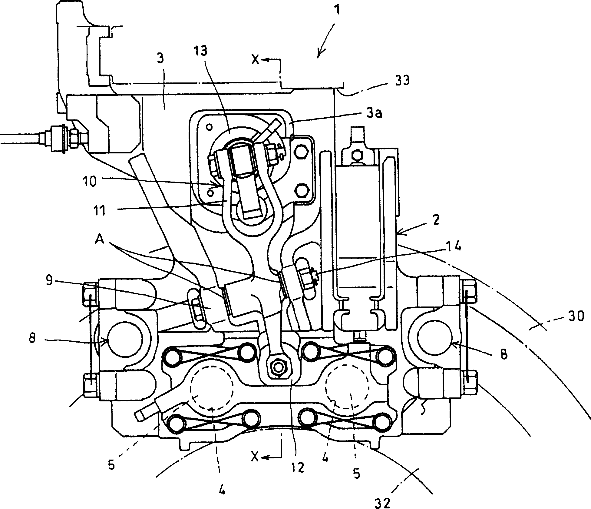
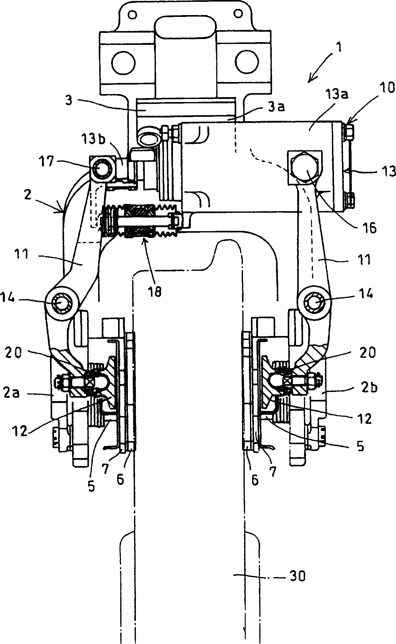
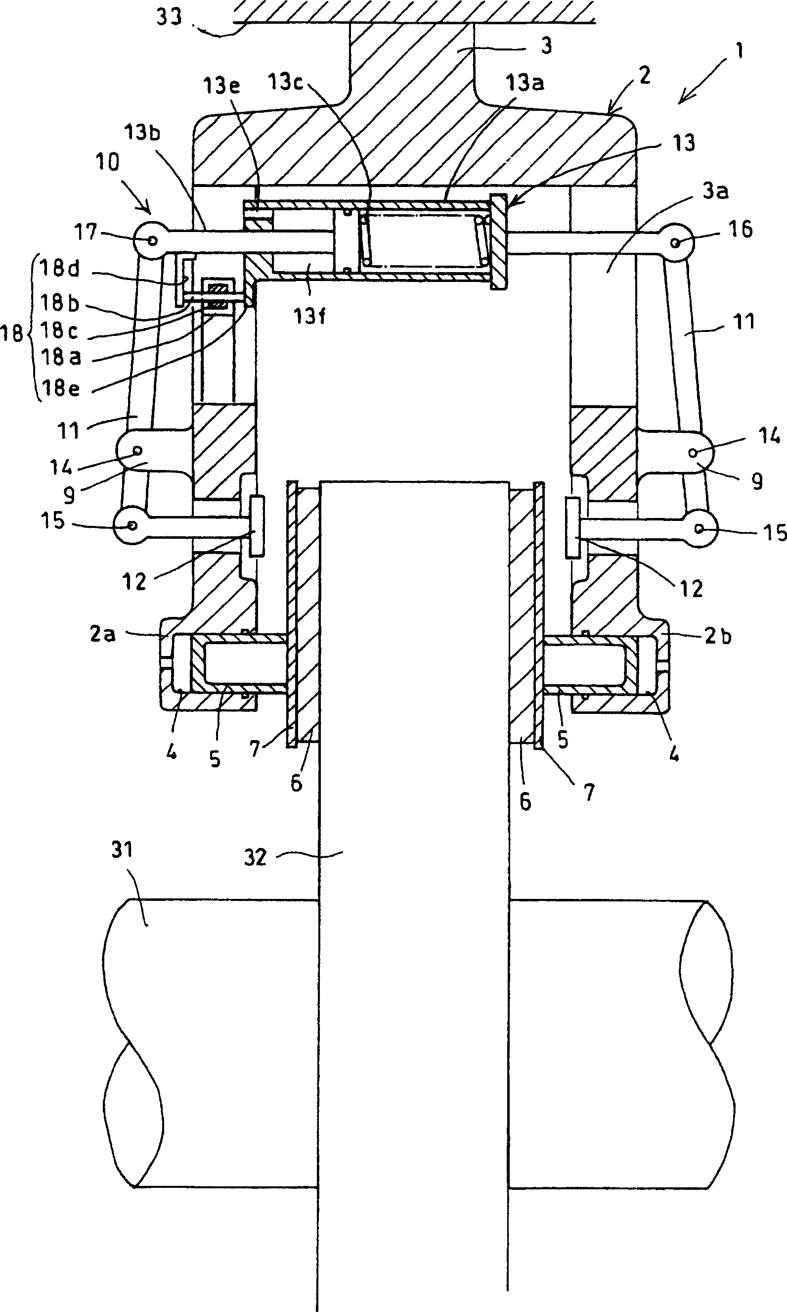
[0028] figure 1 and figure 2 An embodiment of the brake caliper device of the present invention is shown. image 3 It is a pattern diagram for easy understanding of the structure. These figures show an example in which the present invention is applied to a piston opposing type caliper device.

[0029] The caliper body 2 of the relative piston type brake caliper device 1 is installed across the figure 1 , figure 2 Wheels 30 and image 3 The disc 32 on the axle 31 is mounted on a mounting surface 33 forming part of a railway vehicle trolley.

[0030] The caliper body 2 has: a support portion 3 mounted on the mounting surface 33; a cylinder 4 provided on the left and right pliers 2a, 2b in opposite directions; and a piston 5 inserted into each cylinder 4 to be hydraulically actuated. In addition, the caliper body 2 has a sliding mechanism on the rotating-in side and the rotating-out side of the disc 32 to freely support the brake block 6 and the heat insulating gasket 7 e...


PUM


Abstract

The invention solves problems wherein a caliper body moves in the direction of rolling stock width when rolling stock runs, thereby causing wear of a lever turn part, a spring cylinder and a lever interfere with other section, thereby causing noise, and an interference section is damaged in a conventional brake caliper device for railroad rolling stock provided with a parking brake mechanism for swinging the lever supported on the caliper body by the non-restraint spring cylinder and pressing a brake block against a disc by a pressing piece connected with a point of application of the lever. This brake caliper device is provided with a cylindrical case 18a joined with the caliper body 2, a pin 18b inserted into the cylindrical case, an elastic body 18c giving slide resistance to the pin 18b, and a travel resistance imposing means 18 provided with faces 18d, 18e on which both ends of the pin 18b are abutted. Travel resistance is added to the spring cylinder 13 constituting the parking brake mechanism 10 by the travel resistance imposing means 18 to suppress free moving of the spring cylinder by receiving lateral gravity acceleration when the rolling stock runs and suppress its moving by exceeding fixed amount.

Description

technical field [0001] This invention relates to disc brakes used in the braking of railroad vehicles, and more particularly to a disc brake caliper assembly having a parking brake mechanism. Background technique [0002] In a disc brake for a railway vehicle, a piston inserted into a cylinder integrated with a caliper is hydraulically actuated, and the piston presses a brake pad against a disc. The disc brakes for railway vehicles include: caliper floating type: it supports the caliper body in the axial direction of the disc and can slide freely, and presses one of the oppositely arranged brake blocks to the disc through the piston, so that the other brakes. The block is pressed against the disc by the caliper that slides upward on the disc shaft by the reaction force; the piston-opposite type: it fixes the caliper with the oppositely arranged piston on the trolley and presses the oppositely arranged brake block together with the piston . [0003] In Japanese Patent Appli...

Claims


Application Information

Patent Timeline
Patent Type & Authority Applications(China)
IPC IPC(8): B61H5/00B61H13/20F16D55/02F16D55/224F16D65/095F16D65/14F16D65/18
CPCF16D55/2245
Inventor 鹤崎章人小笹昭二中冲秀行麻野吉雄
Owner NIPPON STEEL CORP
Why Eureka
Try Eureka