Marker structure for alignment or overlay, mask pattern defined it and lithographic projector using the same

A technology of mask pattern and lithography projection, applied in the field of lithography projection device

Inactive Publication Date: 2005-02-09
ASML NETHERLANDS BV
View PDF9 Cites 16 Cited by
  • Summary
  • Abstract
  • Description
  • Claims
  • Application Information

AI Technical Summary

Problems solved by technology

On the downside, the overlay control is not as effective: the device will have a different distortion than that measured at the location where the target or marking structure is overlaid

Method used


Image

  • Marker structure for alignment or overlay, mask pattern defined it and lithographic projector using the same
  • Marker structure for alignment or overlay, mask pattern defined it and lithographic projector using the same
  • Marker structure for alignment or overlay, mask pattern defined it and lithographic projector using the same

Examples


Embodiment Construction

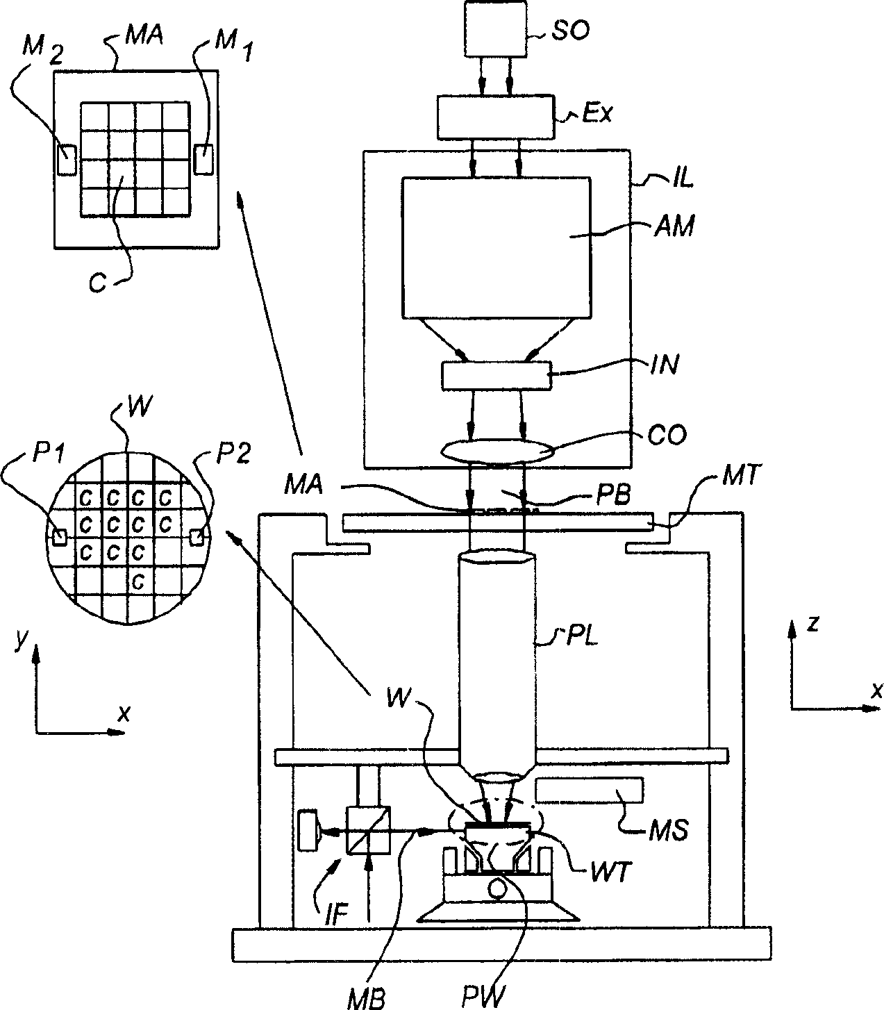
[0055] - figure 1 A lithographic projection apparatus 1 comprising at least one marking structure according to a particular embodiment of the invention is schematically represented. The unit includes:

[0056] - A radiation system Ex, IL for providing a radiation projection beam PB (eg UV radiation). In this particular case, the radiation system also includes the radiation source SO;

[0057] - a first object table (mask table) MT provided with a mask holder for holding a mask MA (eg a reticle) and with first positioning means for precisely positioning the mask relative to the element PL device (not shown) connection;

[0058] - a second object table (substrate table) WT provided with a substrate holder for holding a substrate W (e.g. a resist-coated silicon wafer) and with second positioning means for precise positioning of the substrate relative to the element PL PW connection;

[0059] - A projection system ("lens") PL for imaging the radiation portion of the mask MA o...


PUM


Abstract

A mask pattern for imaging a marking structure on a substrate in lithographic projection, the marking structure being arranged in use for determining optical alignment or overlay, the mask pattern comprising constituent parts to define the marking structure, the composition The part is divided into a plurality of segmented elements (EL; ML), each segmented element has substantially the size of a device feature, the mask pattern includes a segmented shape for each segmented element (EL; ML), which It is characterized in that the mask pattern for the marking structure comprises at least one auxiliary feature (EL_sub) located at a critical part of the segment shape for balancing optical aberrations or optical confinement generated at the critical part in the lithographic projection, which At least one assist feature (EL_sub) has a size substantially smaller than the resolution of the lithographic projection.

Description

technical field [0001] The invention relates to a mask pattern for alignment or overlay as defined in the preamble of claim 1 . Furthermore, the invention relates to a marking structure formed from such a mask pattern. Furthermore, the invention relates to a lithographic projection apparatus using marking structures. Background technique [0002] The invention finds application in the field of lithographic projection apparatus comprising a radiation system for providing a radiation projection beam, a support structure for supporting a patterning member for use in accordance with a desired pattern patterning the projection beam, a substrate table for holding the substrate; and a projection system for projecting the patterned beam onto a target portion of the substrate. [0003] The term "patterning device" should be broadly interpreted as a device capable of imparting a patterned cross-section to an incident radiation beam, wherein said pattern corresponds to a pattern to b...

Claims


Application Information

Patent Timeline
Patent Type & Authority Applications(China)
IPC IPC(8): G03F1/08G03F7/20G03F9/00H01L21/027
CPCG03F7/70633G03F9/7084G03F7/70358G03F9/7076
Inventor J·M·芬德斯M·杜萨R·J·F·范哈伦L·A·C·S·科里纳E·H·J·亨德里克西G·范登伯赫A·H·M·范德霍夫
Owner ASML NETHERLANDS BV
Why Eureka
Try Eureka