Antenna mounting structure

An antenna device and mounting bolt technology, applied in directions such as antennas, antenna supports/mounting devices, antenna parts, etc., can solve the problems of reduced operability, difficulty in aligning the nut 30 and the axis of the mounting bolts, etc.

Inactive Publication Date: 2005-02-09
YOKOWO CO LTD
View PDF1 Cites 5 Cited by
  • Summary
  • Abstract
  • Description
  • Claims
  • Application Information

AI Technical Summary

Problems solved by technology

[0009] However, since there is a large gap between the nut 30 and the mounting bolt 12 when temporary fixing is established, it is sometimes difficult to align the nut 30 and the mounting bolt 12 when the nut 30 is tightened onto the mounting bolt 12. axis, thereby reducing operability

Method used


Image

  • Antenna mounting structure
  • Antenna mounting structure
  • Antenna mounting structure

Examples


Embodiment Construction

[0044] Preferred embodiments of the present invention are described in detail below with reference to the accompanying drawings. Figure 1A to Figure 6B neutralize Figure 7A to Figure 9B Similar components are denoted by the same reference numerals, and repeated descriptions thereof will be omitted.

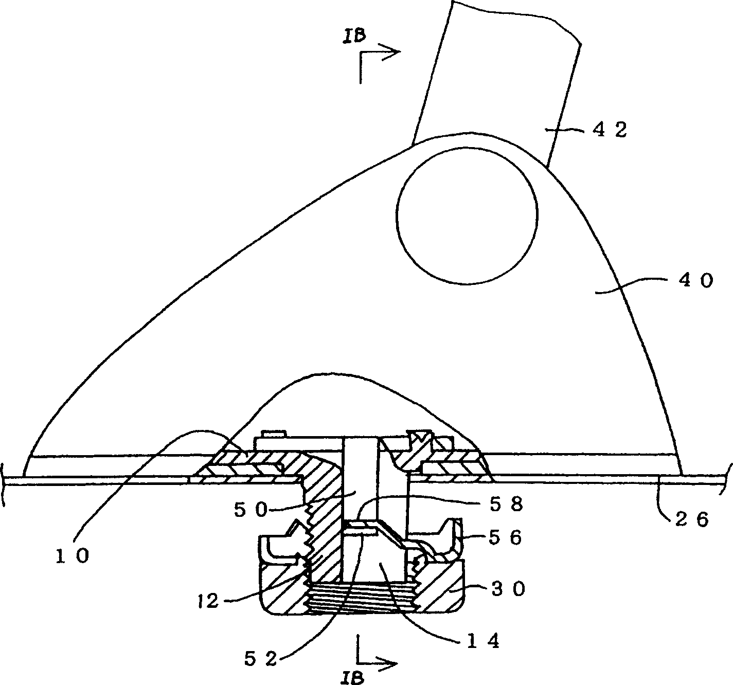
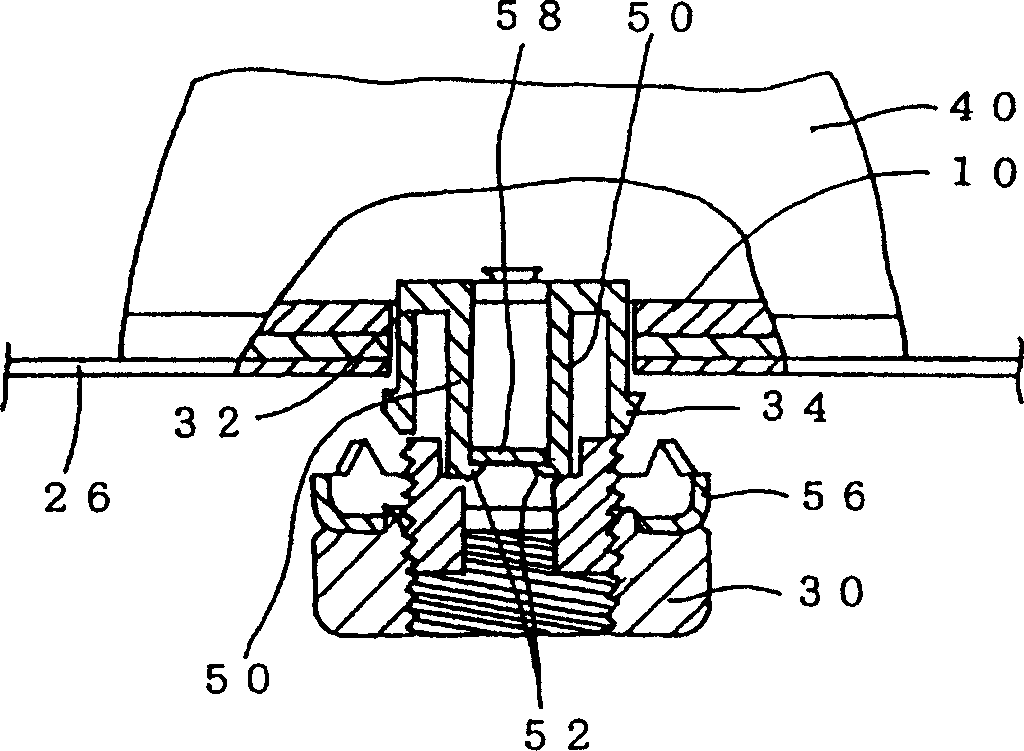
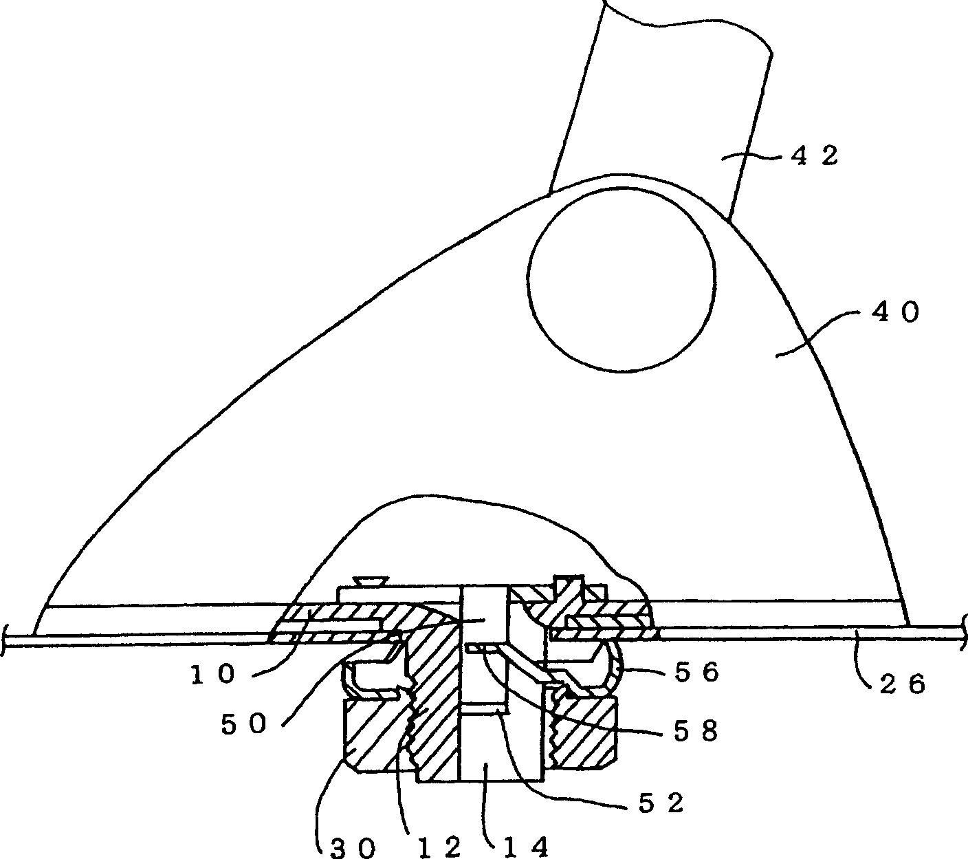
[0045] In this example, if Figure 3A to Figure 3C As shown, the engagement arm 50 is integrally molded with the bracket 32 ​​by a resin material having elasticity. A hook 52 is formed at a tip portion of each engaging arm 50 so that the hook is directed inward.

[0046] Such as Figure 4B with Figure 4C As shown, mounting bolt 12 forms slot 14 and recess 60 that allows engagement arm 50 to move outwardly across the width of slot 14 . In addition, if Figure 4A with Figure 4C As shown, the antenna base forms recesses on both sides of the mounting bolt 12 to allow the support arm 35 to move outward, thus forming through holes 62 on both sides of the slit 14 on the m...


PUM


Abstract

For mounting an antenna device on a first side of a panel body, a mount screw is protruded from the antenna device and formed with a slit extending from a distal end face thereof in an axial direction thereof. A washer has a first engagement member extended from a main body The washer is adapted to be fitted with the mount screw such that the first engagement member is inserted into the slit from the distal end face of the mount screw in a first direction. A second engagement member is provided in the slit, and elastically deformable so as to allow the first engagement member to move within the slit in the first direction. The second engagement member is adapted to engage with the first engagement member at a first position within the slit so as to prevent the first engagement member from moving in a second direction which is opposite to the first direction. A nut is adapted to be screwed to the mount screw while being interconnected with the washer.

Description

technical field [0001] The present invention relates to an antenna mounting structure for mounting an antenna base to a roof panel of a vehicle body or the like. Background technique [0002] In a conventional structure for mounting an antenna device of a motor vehicle to a roof panel of a vehicle body, a mounting bolt protruding downward from an antenna base of the antenna device is inserted into a mounting hole formed in the roof panel, and a A washer with claws is inserted from below into a mounting bolt protruding downward from the top panel, and then a nut is screwed on and secured. [0003] In order to enhance the operability, the washer and the nut with claws are matched and connected with each other and integrated so as to be relatively rotatable around the bolt axis and not separated from each other in the direction of the bolt axis. In order to further enhance operability, Japanese Patent Publication No. 2751146 proposes a method that c...

Claims


Application Information

Patent Timeline
Patent Type & Authority Applications(China)
IPC IPC(8): F16B37/00F16B5/02F16B41/00F16B43/00H01Q1/12H01Q1/22H01Q1/32
CPCH01Q1/3275F16B5/02H01Q1/1214F16B43/00
Inventor 高桥资尚
Owner YOKOWO CO LTD
Why Eureka
Try Eureka