a slot antenna

A slot antenna and slot technology, which is applied to antennas, antenna grounding devices, electrical components, etc., can solve the problems of large occupation area, increased feeding network, complex structure, etc., and achieve a small occupation area, large change space, and simple structure. Effect

Active Publication Date: 2020-03-17
UNIV OF ELECTRONICS SCI & TECH OF CHINA
View PDF9 Cites 0 Cited by
  • Summary
  • Abstract
  • Description
  • Claims
  • Application Information

AI Technical Summary

Problems solved by technology

Most of the applications of reconfigurable technology in slot antennas are frequency reconfigurable. For the reconfigurable pattern, most of the existing technologies and documents are realized by forming an array, which increases the feed network, complex structure, and large footprint.
However, there are few studies on single-slot antennas, and the pattern can only produce small changes on the basis of the original side-firing slot mode.

Method used


Image

  • a slot antenna
  • a slot antenna
  • a slot antenna

Examples


Embodiment 1

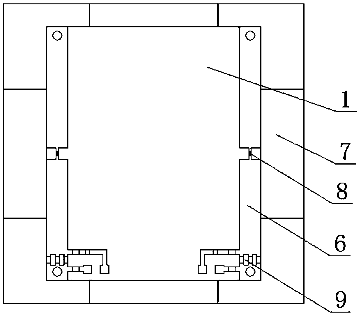
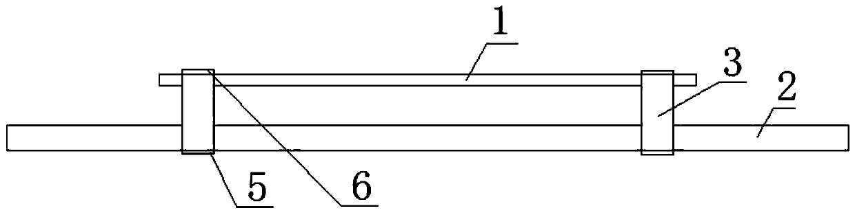
[0028] Such as figure 1 , 2 A double-ring structure shown includes two lower metal strips 5, and an upper metal strip 6 corresponding to the lower metal strip 5, and the two ends of the upper metal strip 6 and the lower metal strip 5 respectively pass through The metal pillars 3 are connected to form two symmetrical parasitic rings, and the parasitic rings are provided with a switch tube for controlling the switching of the parasitic rings and a bias circuit for controlling the switch tube. The two lower metal strips are arranged in parallel. This double ring structure should be used in conjunction with the existing antenna structure. The lower metal strip 5, the upper metal strip 6, and the two metal posts 3 form a parasitic ring, and the two parasitic rings form a parasitic ring pair. The switch tube is controlled by a bias circuit. The on and off of the parasitic loop can be controlled to achieve the working state of the parasitic loop. Each parasitic loop is excited by ...

Embodiment 2

[0030] Based on the principle and structure of the above embodiment, this embodiment refines and optimizes the above structure. Specifically, the switching tube can be realized by using a PIN diode, and it is arranged in the middle of the upper metal strip 6 . It should be noted that those skilled in the art should know that the structure and position setting of the switching tube for realizing parasitic loop on-off control with other structures are within the scope of protection of this solution.

[0031] Such as Figure 4 As shown, the bias circuit can be implemented using the following circuit structure, including a plurality of capacitors connected in parallel, a first inductor connected to one end of the parallel capacitor, a second inductor and a resistor connected in series to the other end of the parallel capacitor. It should be noted that the structure of the bias circuit provided in this embodiment is only a preferred structure, and does not limit its protection scop...

Embodiment 3

[0035] The foregoing embodiments are applicable to antennas of any structure, and a slot antenna is used as an example in this embodiment.

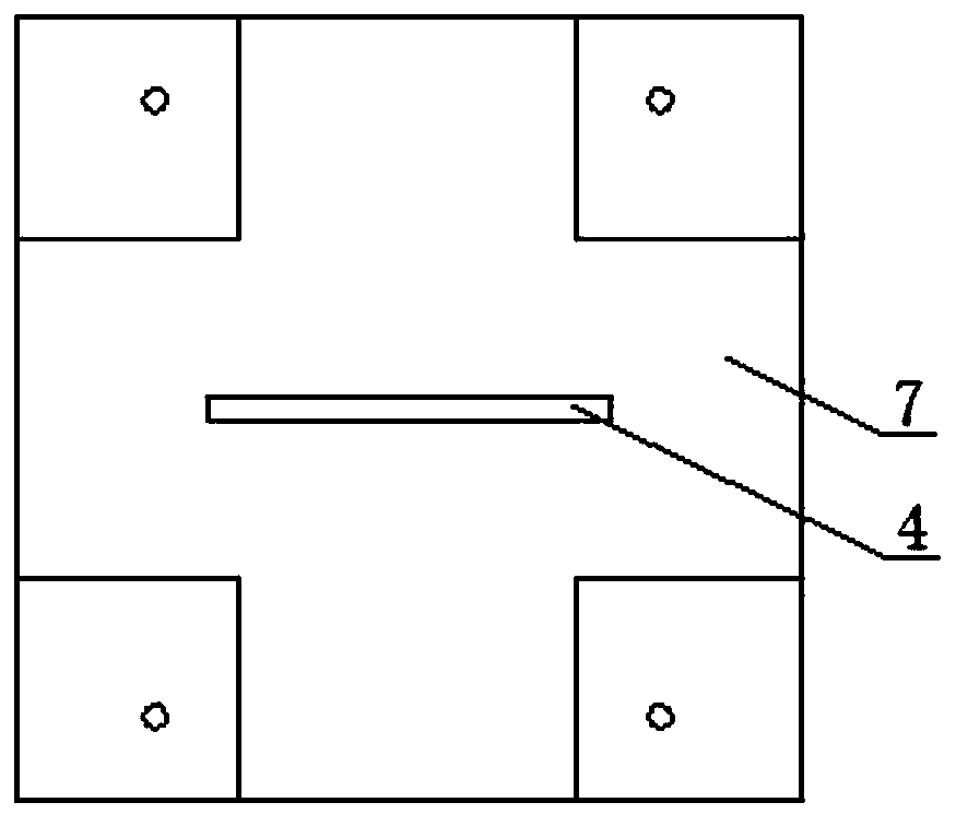
[0036] Such as figure 1 , 2 , a slot antenna shown in 3, comprising a lower dielectric plate 2, an upper dielectric plate 1, a radiation slot 4 arranged on the lower dielectric plate 2, a double-ring structure of any of the above-mentioned embodiments, a lower metal strip 5, an upper metal The strips 6 are respectively arranged on the lower dielectric board 2 and the upper dielectric board 1 .

[0037]The lower dielectric board 2 and the upper dielectric board 1 can be double-layered dielectric boards to facilitate the printing of the metal strips, or can be welded in the air with the metal strips. In this embodiment, the structure of the double-layer dielectric board will be described in detail. The upper and lower surfaces of the lower dielectric board 2 are respectively provided with a metal floor 7 and a lower metal strip 5, the ra...


PUM


Abstract

The invention discloses a double-loop structure and a slot antenna based on the structure. The double-loop structure includes two lower metal strips and an upper metal strip corresponding to the lower metal strips. The upper metal strip and the lower metal strip The two ends of the strip are respectively connected by metal pillars to form two symmetrical parasitic rings, and a switch tube for controlling the switching of the parasitic ring and a bias circuit for controlling the switch tube are arranged on the parasitic rings. It forms parasitic ring pairs by upper metal strips, lower metal strips and metal posts, and realizes pattern reconstruction by controlling the disconnection of parasitic ring pairs. Since it depends on the original working mode of the gap, the pattern points to There is more room for change; in addition, there is no need to increase the number of networks and array elements, and the structure is simple and the occupied area is small.

Description

technical field [0001] The invention relates to the technical field of slot antennas, in particular to a slot antenna. Background technique [0002] For wireless communication terminal equipment, the slot antenna has become a widely used antenna form due to its characteristics of easy integration, simple structure and low cost. However, traditional slot antennas all work in the basic mode of the antenna, that is, the two-way radiation side-firing mode. Expanding the working mode of the basic slot antenna can make an antenna meet the needs of multiple functions and various working environments, and make the antenna have the advantages of high integration and miniaturization. [0003] Reconfigurable technology uses switching diodes to control the feed network or antenna radiator, so that an antenna can have multiple working modes under the control of the switch, and realize the functions of multiple antennas. Most of the applications of reconfigurable technology in slot ante...

Claims


Application Information

Patent Timeline
Patent Type & Authority Patents(China)
IPC IPC(8): H01Q1/38H01Q3/24H01Q19/10H01Q1/48
CPCH01Q1/38H01Q1/48H01Q3/247H01Q19/10
Inventor 赵志钦杨耀辉丁孝翔刘昱朗郭子放
Owner UNIV OF ELECTRONICS SCI & TECH OF CHINA
Why Eureka
Try Eureka