A detachable quenching tank built-in combined shroud

A shroud and quenching tank technology, applied in quenching devices, heat treatment equipment, manufacturing tools, etc., can solve the problems of unadjustable outlet height of flow restrictor, low applicability of workpiece shape, small water inlet area, etc. Low cost, good applicability, and the effect of improving quenching quality

Active Publication Date: 2018-09-11
SHANGHAI JIAO TONG UNIV
View PDF3 Cites 0 Cited by
  • Summary
  • Abstract
  • Description
  • Claims
  • Application Information

AI Technical Summary

Problems solved by technology

However, the height of the outlet of the restrictor plate is fixed and cannot be adjusted, and it is placed horizontally at the lower part of the tank. As the height increases, the flow will diverge more, and at the same time, it will cause a considerable degree of pressure head loss.
[0007] The Chinese invention patent with the application number 200910053752.3 discloses a slit effect quenching fixture. By using the slit effect, the medium flow rate on the surface around the workpiece is higher than the average flow rate in the quenching tank, thereby achieving the effect of increasing the cooling rate of the workpiece. However, the fixture The shape of the workpiece is required to be relatively regular, the applicability to the shape of the workpiece is low, and the scope of application is small. When used, the fixture needs to be put in and out of the furnace or hung up after heating, and the operation is complicated.
Moreover, the area of ​​the water inlet at the bottom of the slit effect quenching fixture is small, and it is impossible to collect the water flow on the entire section of the quenching tank around the workpiece

Method used


Image

  • A detachable quenching tank built-in combined shroud
  • A detachable quenching tank built-in combined shroud
  • A detachable quenching tank built-in combined shroud

Examples


Embodiment 1

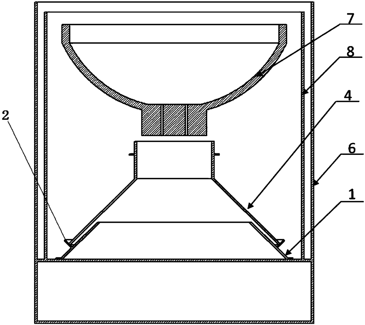
[0038] Such as figure 1 As shown, this embodiment includes: a quenching tank 6, a quenching inner tank 8, a conical base 1, and a single cone segment shroud assembly 4, such as Figure 4 As shown, the single cone segment shroud assembly 4 includes a cone segment 41 and a vertical outlet segment 42 arranged sequentially from bottom to top. The bottom diameter and taper of the cone segment 41 are adapted to the conical base 1, and the vertical outlet The shape and size of the section 42 are adapted to the workpiece to be quenched. The conical base 1 is fixed on the lower part of the quenching tank 6, and the conical surface forms a certain angle with the horizontal plane, which can reduce the loss of flow and speed caused by the horizontal deflector structure. The single-cone segment shroud assembly 4 is placed on the conical base 1 and adopts a detachable movable connection.

[0039]The quenching tank 6 described in this embodiment has a diameter of Φ11m, a height of 11m, an ...

Embodiment 2

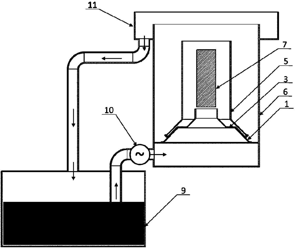
[0041] Such as figure 2 As shown, the present embodiment includes: a quenching tank 6, a conical base 1, a step-type shroud assembly 3, and a cylindrical shroud assembly 5, wherein: the conical base 1 is fixed on the bottom of the quenching tank 6, and the conical surface and The bottom surface of the quenching tank is at a certain angle, which can reduce the flow and speed loss caused by the horizontal deflector structure. The conical base 1 is connected with the quenching tank 6 by fixing bolts, which is convenient for adjustment and easy to assemble and disassemble. The stepped windshield assembly 3 and the cylindrical windshield assembly 5 are placed on the conical base 1 and are connected in a detachable manner.

[0042] In this embodiment, the quenching tank 6 has a diameter of Φ8m and a height of 10m. The quenching workpiece 7 is a long-axis workpiece with a diameter of Φ1.4m and a height of 6m. In this embodiment, a detachable quenching tank built-in combined shroud...

Embodiment 3

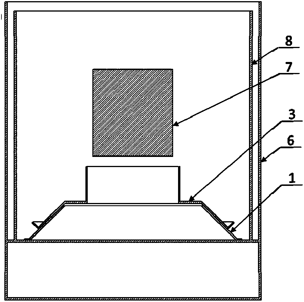
[0047] Such as image 3 As shown, this embodiment includes: a quenching tank 6, a conical base 1, and a stepped shroud assembly 3, wherein: the conical base 1 is fixed on the bottom of the quenching tank 6, and the conical surface forms a certain angle with the bottom surface of the quenching tank, which can reduce the Flow and velocity losses due to small horizontally placed deflector structures. The conical base 1 is connected with the quenching tank 6 by fixing bolts, which is convenient for adjustment and easy to assemble and disassemble. The step-type shroud assembly 3 is placed on the conical base 1 and adopts a detachable movable connection.

[0048] The quenching tank 6 described in this embodiment has a diameter of Φ11 m and a height of 8 m, and 12 bottom inserted propellers are installed at the bottom to make the water in the quenching tank flow. The quenching workpiece 8 is a square workpiece, and its size is 3.5m×3.5m×3.5m. A stepped wind deflector assembly 3 is...


PUM

PropertyMeasurementUnit
diameteraaaaaaaaaa

Abstract

The invention relates to a detachable quenching tank built-in combination type flow guiding cover. The flow guiding cover comprises a conical base fixed to the lower part of a quenching tank and a flow guiding cover unit detachably arranged on the conical base in a sleeving manner in a vertical direction, wherein the flow guiding cover unit comprises at least one flow guiding cover assembly; the flow guiding cover assembly comprises a conical body section and a vertical outlet section which are sequentially arranged from the bottom to the top; the bottom diameter and conicity of the conical body section are matched with those of the conical base, and the shape and size of the vertical outlet section of each flow guiding cover assembly are matched with those of a to-be-quenched workpiece; and the outer side surface of the conical base is provided with a locating cone, and the bottom edge of the flow guiding cover assembly is pressed against the locating cone and is fixedly connected with the conical base. Compared with the prior art, the flow guiding cover has the advantages that the structure is flexible, can be timely changed and regulated, is convenient to assemble and disassemble and has great applicability; the defects of the existing fixed type flow guiding and equalizing device can be overcome under the condition of ensuring economical benefit; and the universality of the quenching tank is improved, and the application prospect is great.

Description

technical field [0001] The invention belongs to the technical field of heat treatment of metal materials, and relates to a combined wind deflector, in particular to a built-in combined wind deflector in a detachable quenching tank. Background technique [0002] Quenching is an important process in the heat treatment of metal materials. It is a process of heating the workpiece to an appropriate temperature and maintaining it for a period of time, and then immersing it in a quenching medium for rapid cooling to improve the hardness and wear resistance of the workpiece. In the quenching process, good cooling intensity is required to ensure the quality of the quenched workpiece. The cooling intensity depends not only on the thermophysical properties of the quenching medium itself, but also on the flow state of the quenching medium. That is, the greater the flow velocity of the quenching medium, the deeper the hardened layer and the stronger the cooling capacity; the more uniform...

Claims


Application Information

Patent Timeline
Patent Type & Authority Patents(China)
IPC IPC(8): C21D1/63
CPCC21D1/63
Inventor 顾剑锋王婧骆晓萌潘健生
Owner SHANGHAI JIAO TONG UNIV
Why Eureka
Try Eureka