Hollow cavity shuttering member

A cavity mold and component technology, which is applied to building components, building structures, floor slabs, etc., can solve the problems of inconvenient assembly line production, low production efficiency, and high cost

Inactive Publication Date: 2005-02-16
邱则有
View PDF3 Cites 18 Cited by
  • Summary
  • Abstract
  • Description
  • Claims
  • Application Information

AI Technical Summary

Problems solved by technology

But this type of cavity formwork member is inconvenient to manufacture, the production efficiency is low, it is not convenient for assemb

Method used


Image

  • Hollow cavity shuttering member
  • Hollow cavity shuttering member
  • Hollow cavity shuttering member

Examples


Embodiment Construction

[0036] The present invention will be further described below in conjunction with the accompanying drawings and embodiments.

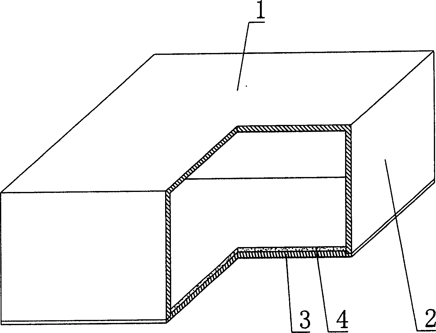
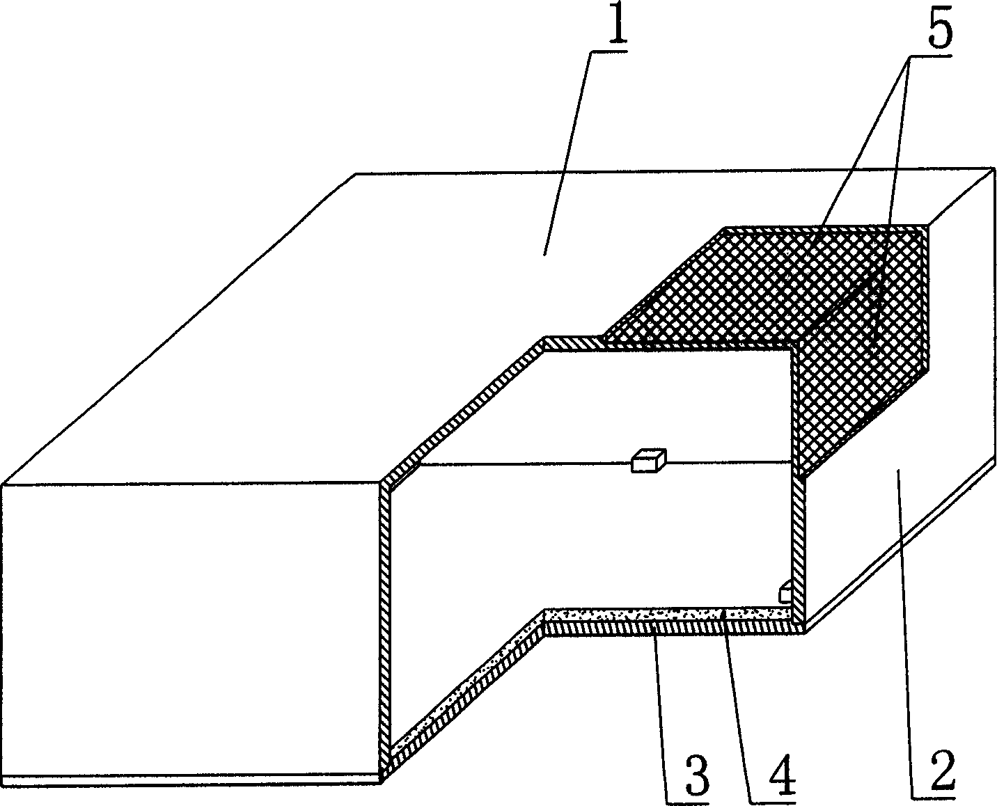
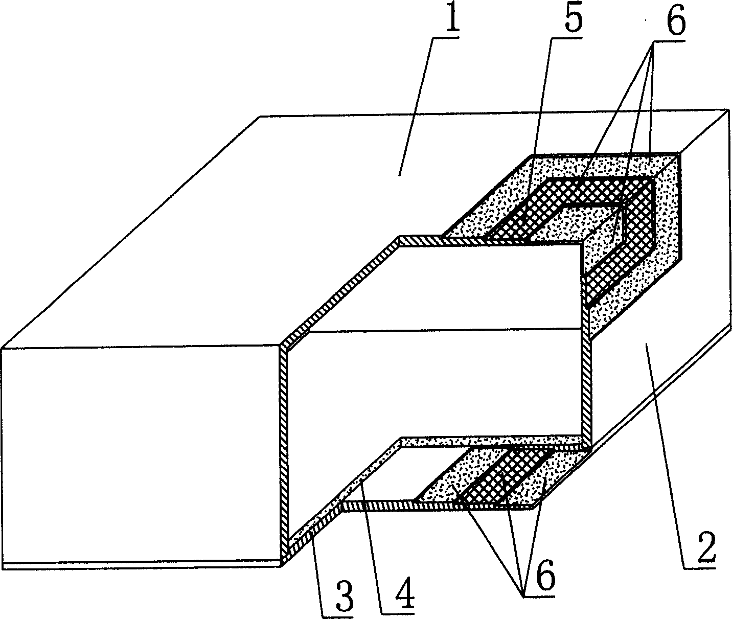
[0037] As shown in the accompanying drawings, the present invention includes an upper plate 1, surrounding side walls 2, and lower bottom 3, and the upper plate 1, surrounding side walls 2, and lower bottom 3 form a polyhedral cavity formwork member, which is characterized in that the cavity formwork At least one side of the component is provided with a superimposed template 4 . figure 1 It is a structural schematic diagram of Embodiment 1 of the present invention. In the accompanying drawings, 1 is an upper plate, 2 is a surrounding side wall, 3 is a lower bottom, and 4 is a template. In the following drawings, those with the same number have the same description. Such as figure 1 As shown, the upper plate 1, the surrounding side walls 2 and the lower bottom 3 enclose a polyhedral cavity formwork member, and the lower bottom 3 is superimposed with a ...


PUM


Abstract

A cavity die shell member includes a top plate, surrounding side walls and a bottom forming a polyhedron cavity shell member characterizing in setting a laminated form at on a side of themember, thus, an open cavity shell member can be processed and the open side is up ward, then a form is suspended on put on the opening side to seal it, after the mushy material is hardened it is cured for specified time to get a cavity shell member with a laminated form.

Description

(1) Technical field [0001] The present invention relates to a cavity formwork member. (2) Background technology [0002] At present, the cast-in-place concrete hollow floor is a widely used floor structure. The lightweight permanent tire molds filled in it include various hollow tubes and boxes, and the boxes are hollow or solid. For example, the patent No. ZL99249798.1, which the applicant applied for on November 29, 1999, is a utility model patent named "fiber-reinforced thin-walled member for reinforced concrete filling", which discloses a thin-walled formwork member, including an upper plate, The surrounding side walls, the lower bottom, and the upper plate, the surrounding side walls and the lower bottom form a polyhedral cavity. Another example is the patent No. ZL00203695.9 applied by Liang Jun, Shijiazhuang City, Hebei Province on February 23, 2000, and the name is called "combined concrete hidden rib floor cover plate" utility model patent, which discloses a formwo...

Claims


Application Information

Patent Timeline
IPC IPC(8): E04B5/36
Inventor 邱则有
Owner 邱则有
Why Eureka
Try Eureka