Self heating and thermal insulating cup
A thermos cup and self-heating technology, which is applied in the field of thermos cups, can solve problems such as poor heat preservation effect, achieve the effects of infinitely extending the heat preservation time, improving living conditions in the field, and reducing energy consumption
- Summary
- Abstract
- Description
- Claims
- Application Information
AI Technical Summary
Problems solved by technology
Method used
Image
Examples
Embodiment 1
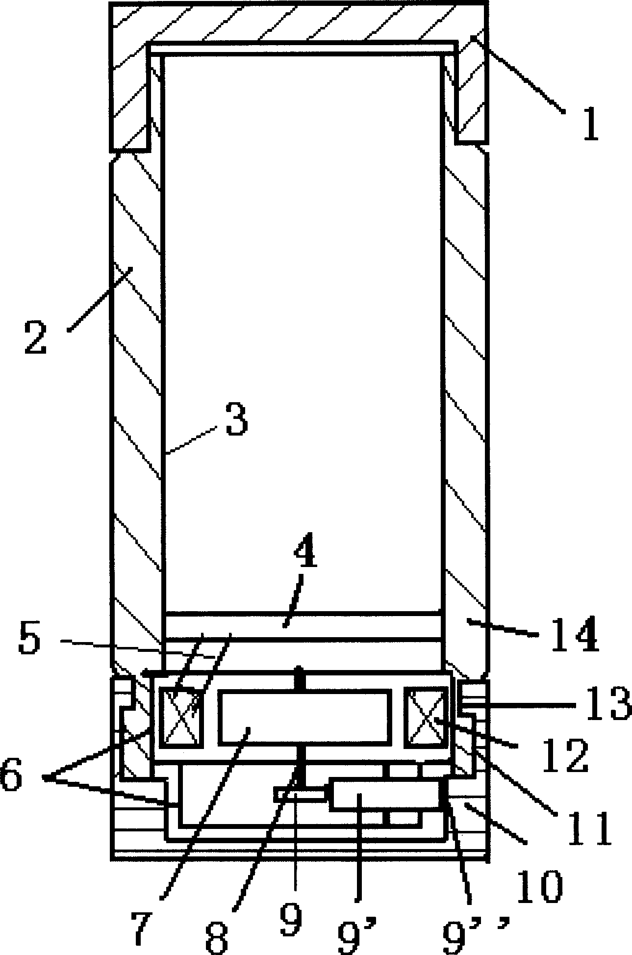
[0022] figure 1 Among them, a self-heating thermos cup includes a cup cover 1, a cup body 2, an inner container 3, and a cup bottom 10. An electric heating plate 4 is fixed at the bottom of the inner container 3, and the electric heating plate 4 and the heat-conducting inner container 3 The bottom of the cup is closely contacted, the cup bottom 10 and the cup body 2 are connected with the annular convex groove 13 through the annular groove 11, a bracket 6 is fixed on the lower part of the cup body 2 and the corresponding position of the cup bottom 10, and a bracket 6 is installed on the bracket 6. The generating coil 12, the shaft of the permanent magnet 7 and the transmission gear 9 are the rotating main shaft 8, and the rotating main shaft 8 is movably installed on the support 6, the transmission gears 9, 9' mesh with each other, and the gear shaft of the transmission gear 9' is fixed on the support 6, The permanent magnet 7 is fixed on the rotating main shaft 8 and is locat...
Embodiment 2
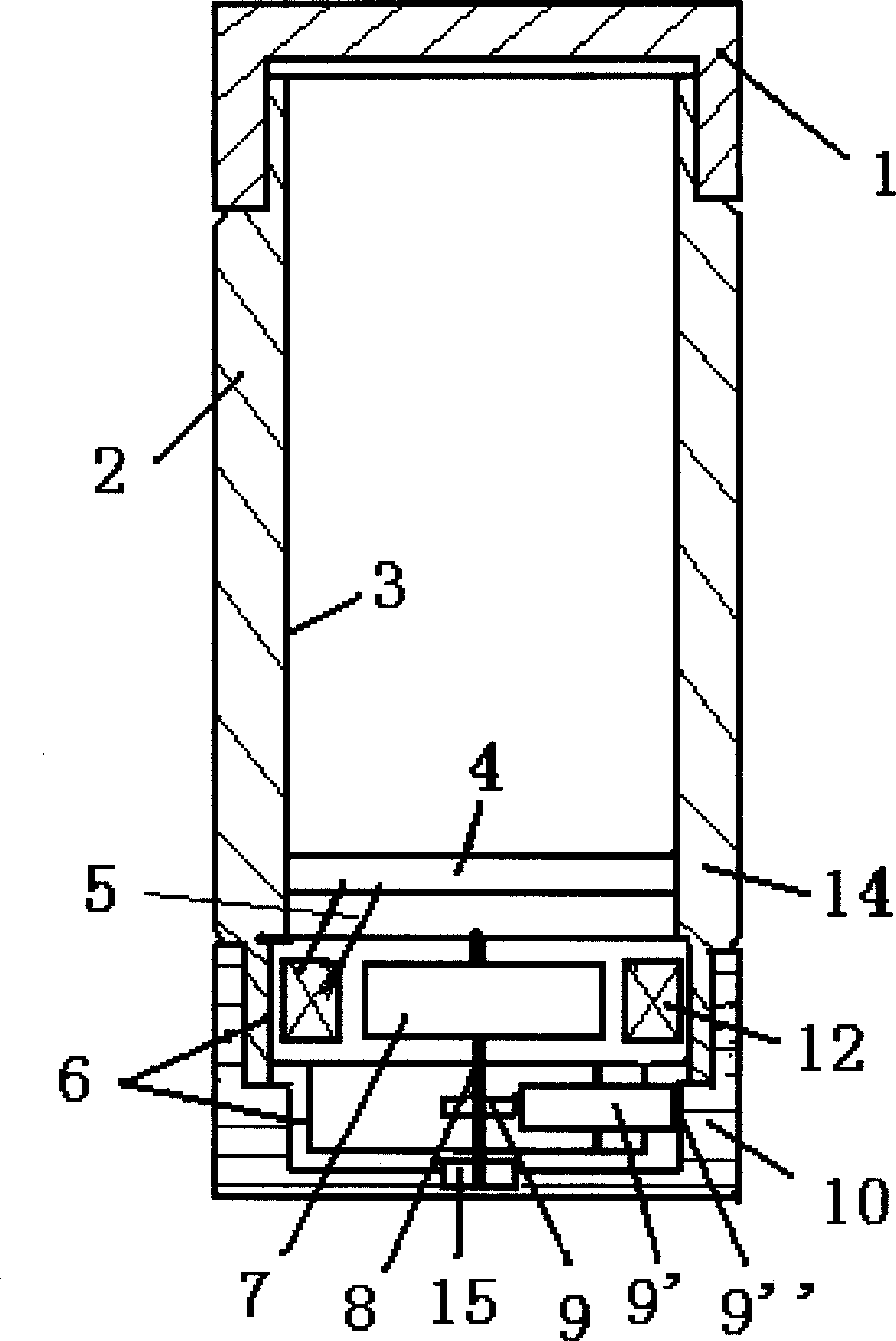
[0024] figure 2 Among them, a self-heating thermos cup includes a cup cover 1, a cup body 2, an inner container 3, and a cup bottom 10. An electric heating plate 4 is fixed at the bottom of the inner container 3, and the electric heating plate 4 and the heat-conducting inner container 3 The bottom of the cup body 2 is in close contact with the bottom of the cup body 2 and a bracket 6 is fixed at the position corresponding to the bottom of the cup 10, and a generator coil 12 is installed on the bracket 6. The shafts of the permanent magnet 7 and the transmission gear 9 are the rotating main shaft 8 and The main shaft 8 is movably installed on the bracket 6, the transmission gears 9, 9' mesh with each other, the gear shaft of the transmission gear 9' is fixed on the bracket 6, the permanent magnet 7 is fixed on the rotating main shaft 8 and is located in the ring of the generator coil 12, and the generator coil 12 and the electric heating plate 4 are connected with the connecti...
Embodiment 3
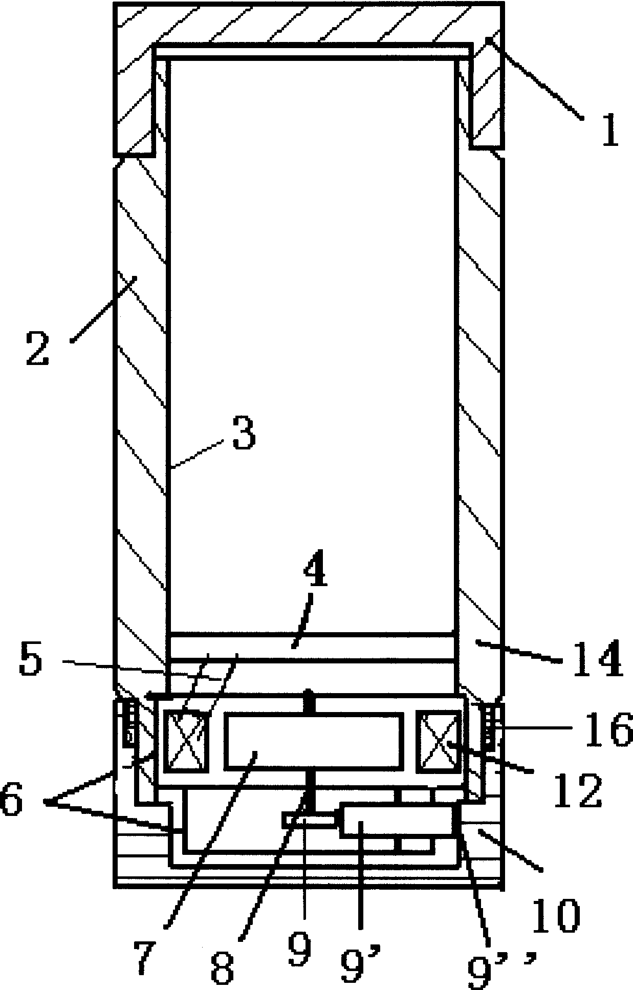
[0026] image 3 Among them, a self-heating thermos cup includes a cup cover 1, a cup body 2, an inner container 3, and a cup bottom 10. An electric heating plate 4 is fixed at the bottom of the inner container 3, and the electric heating plate 4 and the heat-conducting inner container 3 The bottom of the cup is closely contacted, the cup bottom 10 is connected with the cup body 2 through a large rotating bearing 16, a bracket 6 is fixed on the corresponding position of the bottom of the cup body 2 and the cup bottom 10, and a power generation coil 12 is installed on the bracket 6, permanently The axle of magnet 7 and transmission gear 9 is rotating main shaft 8, and rotating main shaft 8 is installed on the support 6 movably, and transmission gear 9,9 ' meshes with each other, and the gear shaft of transmission gear 9 ' is fixed on support 6, and permanent magnet 7 is fixed on Rotate the main shaft 8 and be located in the generator coil 12 rings, the generator coil 12 is conne...
PUM
 Abstract
Description
Claims
Application Information
 - R&D
- Intellectual Property
- Life Sciences
- Materials
- Tech Scout
- Unparalleled Data Quality
- Higher Quality Content
- 60% Fewer Hallucinations
Browse by: Latest US Patents, China's latest patents, Technical Efficacy Thesaurus, Application Domain, Technology Topic, Popular Technical Reports.
© 2025 PatSnap. All rights reserved.Legal|Privacy policy|Modern Slavery Act Transparency Statement|Sitemap|About US| Contact US: help@patsnap.com


