Producing device and its producing method for capillary tissue micro groove of heat pipe inner wall

A technology for manufacturing equipment and micro-grooves, applied in the field of the manufacture of capillary micro-grooves and capillary micro-grooves, can solve the problem of inconvenient operation, poor contact between the metal woven mesh and the inner wall of the heat pipe, damage to the chip, etc. problem, to achieve the effect of excellent heat transfer performance, reliable capillary structure, and not easy to damage

Inactive Publication Date: 2005-03-02
SOUTH CHINA UNIV OF TECH
View PDF0 Cites 10 Cited by
  • Summary
  • Abstract
  • Description
  • Claims
  • Application Information

AI Technical Summary

Problems solved by technology

The capillary metal powder sintered structure is not only expensive, but also complex in process, and adds extra weight to the heat pipe, especially after the capillary structure is sintered, the mandrel is easy to damage the sintered powder structure when it is drawn out, resulting in a decline in the performance of the heat pipe; for small thin-walled The heat pipe is extremely inconvenient to operate when the metal braided wire mesh is embedded in the tube. Moreover, the metal braided mesh is not in close contact with the inner wall of the heat pipe, which leads to an incr

Method used


Image

  • Producing device and its producing method for capillary tissue micro groove of heat pipe inner wall
  • Producing device and its producing method for capillary tissue micro groove of heat pipe inner wall
  • Producing device and its producing method for capillary tissue micro groove of heat pipe inner wall

Examples


Embodiment Construction

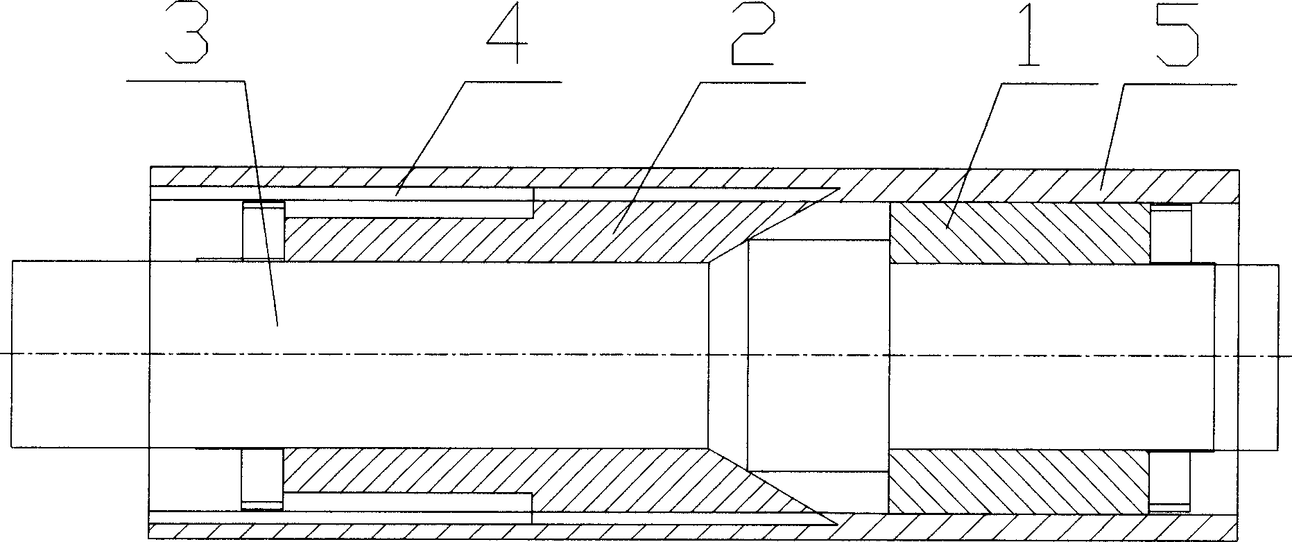
[0025] like figure 1 As shown, the manufacturing equipment of the heat pipe with capillary micro-grooves on the inner wall of the present invention is mainly composed of a positioning rod 1, a cutter 2 and a pull rod 3; .

[0026] When working, fix the base tube 5 of the heat pipe of the workpiece on the frame, make the pull rod pass through the base tube, be clamped by the traction device and drive the pull rod 3 to move, and when the pull rod 3 moves from one end of the base tube to the other end under the action of tension, The positioning rod 1 plays the role of positioning and guiding, and drives the cutter 2 to advance in the axial direction, and the cutting edge on the cutter plows the capillary micro-groove structure 4 on the inner wall of the base tube 5 .

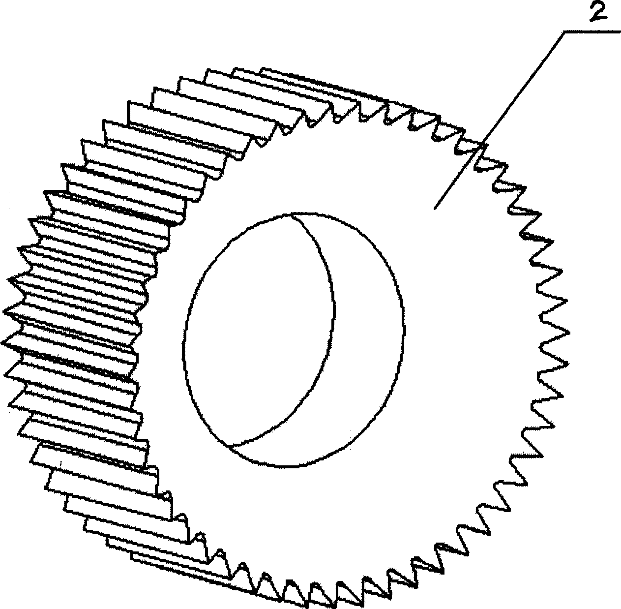
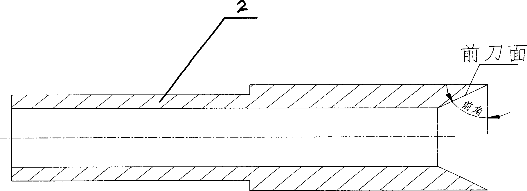
[0027] like figure 2 , 3 As shown, the tool is cylindrical, and several alternate cutting edges and grooves are evenly distributed along the circumference of the outer surface, and the rake face is processed i...


PUM


Abstract

The device for making the micro capillary grooves in the inner wall of heat pipe mainly consists of positioning rod, cutter and pull rod. The positioning rod is mounted on one side surface of the pull rod, and the cutter is mounted on the other side surface of the pull rod. The present invention also relates to the method of making the micro capillary grooves in the inner wall of heat pipe with the said device. The making process features that the pull rod is drawn axially to drive the cutter to broach in the inner wall of the heat pipe base and the inner wall surface of the heat pipe base cracks to form capillary micro grooves. The improved capillary structure makes the heat pipe possess excellent heat transferring performance and lowers the production cost of heat pipe.

Description

technical field [0001] The invention relates to a manufacturing device of a heat transfer element of an electronic device, in particular to a manufacturing device of capillary microgrooves on the inner wall of a heat pipe. [0002] The invention also relates to a method for manufacturing the capillary micro-grooves on the inner wall of the heat pipe. Background technique [0003] At present, electronic products tend to be more high-performance, multi-functional, and lighter, especially electronic computer products. With the continuous improvement of the integration of electronic chips, the accumulated energy per square inch will continue to increase according to Moore's law, bringing fatal High heat flux, if the accumulated heat cannot be discharged in time, it will lead to serious failure of electronic devices, thus restricting the further development and application of electronic products. [0004] Conventional heat sink technology for electronic...

Claims


Application Information

Patent Timeline
IPC IPC(8): B23D37/22B23D43/02
Inventor 汤勇陈平潘敏强陆龙生刘亚俊万珍平
Owner SOUTH CHINA UNIV OF TECH
Why Eureka
Try Eureka