
Method for preparing hollow nanofiber, hollow nanofiber and catalyst composition for preparing hollow nanofiber

A technology of nanofibers and compounds, applied in the field of hollow nanometers, which can solve the problems of difficult control of carbon nanotube diameter, inability to control the size, etc.

Inactive Publication Date: 2005-03-09
TORAY IND INC
View PDF0 Cites 4 Cited by
  • Summary
  • Abstract
  • Description
  • Claims
  • Application Information

AI Technical Summary

Problems solved by technology

The size of the micropores at the powder interface and crystal interface cannot be controlled like the micropores of zeolite itself, so it is difficult to control the diameter of the generated carbon nanotubes, etc.

Method used


Image

  • Method for preparing hollow nanofiber, hollow nanofiber and catalyst composition for preparing hollow nanofiber
  • Method for preparing hollow nanofiber, hollow nanofiber and catalyst composition for preparing hollow nanofiber
  • Method for preparing hollow nanofiber, hollow nanofiber and catalyst composition for preparing hollow nanofiber

Examples


Embodiment 1

[0173] [Synthesis of heat-resistant zeolite]

[0174] 164 g of distilled water were added to 18.9 g of piperazine hexahydrate (manufactured by Aldrich) and 5.2 g of tetrapropylammonium bromide (manufactured by Aldrich), and stirred. Stir while heating until dissolved. Further, 11.7 g of wet silica (manufactured by Aldrich) was added thereto, and heated to 80° C. to obtain a transparent aqueous solution. This was added to a Teflon-lined autoclave and heated at 150°C for 5 days. After that, it is cooled, filtered, washed with water, dried, and then baked at 550°C in air.

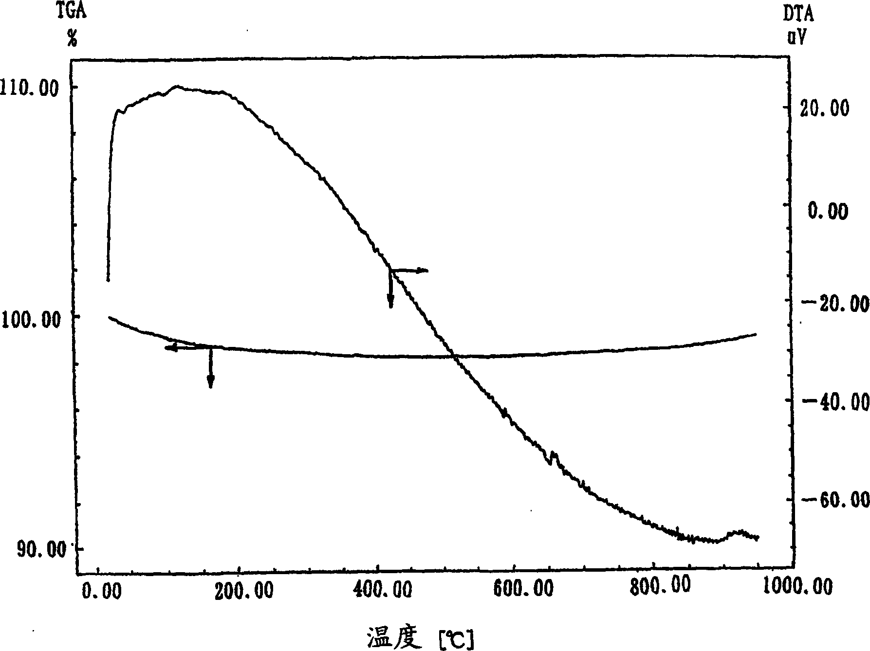
[0175] The X-ray diffraction (XRD) measurement of the obtained powder revealed that it was silicalite-1 having an MFI structure. With the thermal analysis device DTG-50 that Shimadzu Corporation manufactures, this powder is heated to 900 ℃ with the rate of temperature rise of 5 ℃ / min in the nitrogen flow of 50ml / min, and exothermic peak does not appear in the DTA curve ( figure 1 ).

[0176] [Metal salt att...

Embodiment 2

[0184] [Heat resistance of crystalline titanium silicate]

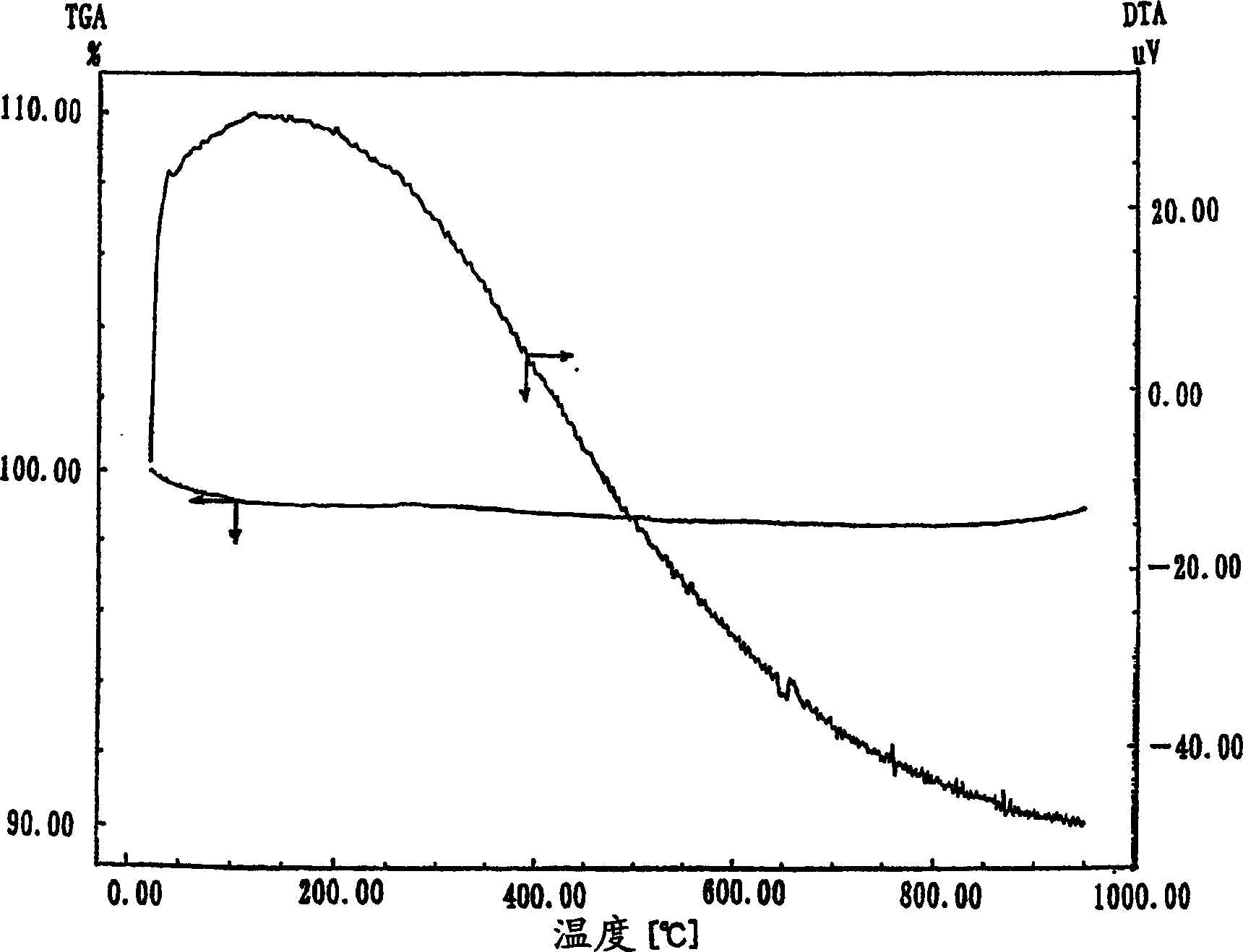
[0185] The X-ray diffraction (XRD) measurement of titanium silicate powder (Si / Ti ratio: 50) purchased from Eno-Chem Kitat Co., Ltd. revealed that it was TS-1 having an MFI structure. With the thermal analysis device DTG-50 that Shimadzu Corporation manufactures, this powder is heated to 900 ℃ with the rate of temperature rise of 5 ℃ / min in the nitrogen flow of 50ml / min, and exothermic peak does not appear in the DTA curve ( figure 2 ).

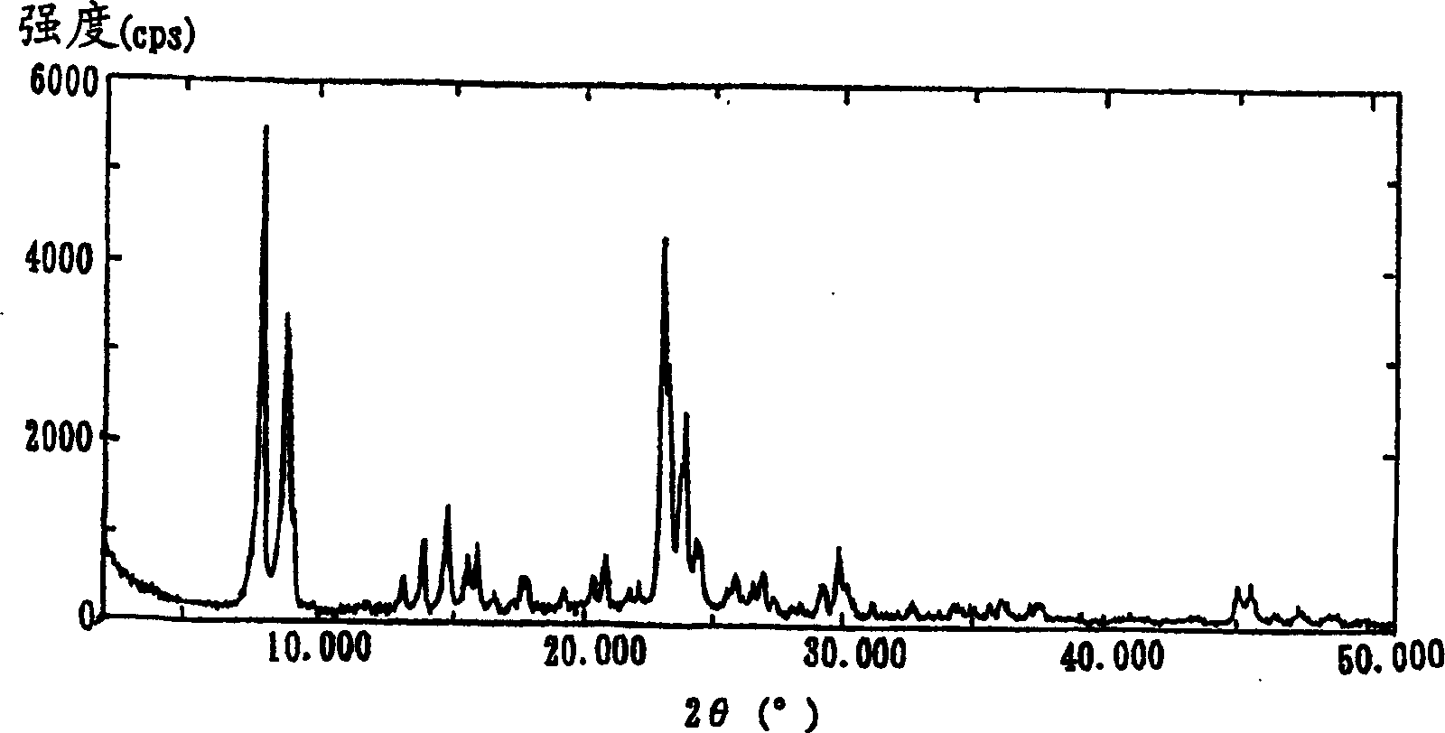
[0186] This zeolite was calcined at 900° C. for 30 minutes, and then carried out XRD diffraction, then the peak of MFI type zeolite remained ( image 3 ).

[0187] [Metal salt attached to heat-resistant zeolite]

[0188] 0.08 g of ferrous acetate (manufactured by Aldrich) and 0.11 g of cobalt acetate 4 hydrate (manufactured by Nacalaitesque) were added to 7 ml of methanol (manufactured by Nacalaitesque), and suspended for 10 minutes using an ultrasonic cleaner. 1.0 g of the abov...

Embodiment 3、4

[0219] Embodiment 3, 4, comparative example 2

[0220] Using a thermal analysis device DTG-50 manufactured by Shimadzu Corporation, the zeolite HSZ-390HUA (designated as zeolite 1) prepared by Tosoh was heated to 900°C at a heating rate of 5°C / min in a nitrogen flow of 50ml / min. , resulting in an exothermic peak in the DTA curve ( Figure 11 ).

[0221] The zeolite was roasted at 900° C. for 30 minutes in dry air, and then it was measured by XRD. As a result, the structure of the Y-type zeolite was maintained, but the peak became steeper and larger than that before roasting (XRD before roasting: Figure 13 , XRD after roasting: Figure 14 ). It is believed that some structural changes occurred during the temperature increase to 900°C.

[0222] Using a thermal analysis device DTG-50 manufactured by Shimadzu Corporation, heat zeolite HSZ-390HUA (designated as zeolite 2) at 900°C for 30 minutes in a nitrogen flow of 50ml / min at a heating rate of 5°C / min to 900°C, the result ...


PUM

PropertyMeasurementUnit
thicknessaaaaaaaaaa
diameteraaaaaaaaaa
diameteraaaaaaaaaa

Abstract

A method for preparing hollow nanofibers having carbon as a primary component, which comprises contacting a carbon-containing compound with a catalyst at a temperature of 500 to 1200 DEG C, wherein as the catalyst use is made of a catalyst comprising a zeolite exhibiting the thermal resistance at 900 DEG C and, supported thereon, a metal; a catalyst comprising a metallosilicate zeolite containing a heteroatom except aluminum and silicon in the structural framework thereof and, supported thereon, a metal; a catalyst comprising a supporting material and, supported thereon, fine cobalt particles exhibiting a binding energy of a cobalt 2P3 / 2 electron of 779.3 to 781.0 eV, as measured by the X-ray photoelectron spectroscopy; a catalyst comprising a supporting material and, supported thereon, fine cobalt particles exhibiting a cobalt atom ratio in the surface of the supporting material of 0.1 to 1.5%, as measured by the X-ray photoelectron spectroscopy under a condition of 10 kV and 18 mA; a catalyst comprising a supporting material and, supported thereon, fine cobalt particles exhibiting a weight ratio of cobalt to a second metal component (weight of cobalt / weight of the second metal component) of 2.5 or more; or a catalyst comprising a zeolite having a film form and, supported on the surface thereof, a metal.

Description

technical field [0001] The present invention relates to a method for preparing hollow nanofibers, hollow nanofibers and a catalyst composition for preparing hollow nanofibers. More specifically, the present invention relates to a method for preparing hollow nanofibers, and more specifically, the present invention relates to finer thickness, fewer defects in graphite layers, and the availability of multilayer nanocarbons. Method for preparing hollow nanofibers of tubes, hollow nanofibers obtained by the method, and catalyst composition for preparing hollow nanofibers. Background technique [0002] Representative examples of hollow nanofibers include carbon nanotubes. The carbon nanotubes have a cylindrical shape formed by rolling up one side of graphite. We make one layer of rolled carbon nanotubes into single-layer carbon nanotubes, and two or more layers of rolled up carbon nanotubes into multilayer nanotubes. carbon tube. The carbon nanotubes have high mechanical strengt...

Claims


Application Information

Patent Timeline
Patent Type & Authority Applications(China)
IPC IPC(8): B01J29/072B01J29/14B01J29/46B01J29/86B01J29/88B01J29/89B01J35/06C01B31/02D01F9/127
CPCB01J29/46C01B2202/34B01J2229/186C01B31/0233C01B2202/02C01B2202/06C01B2202/04B01J29/89C01B2202/36B82Y40/00B01J29/072B01J29/86B01J29/146B01J29/88B01J29/046B82Y30/00B01J35/065D01F9/127C01B32/162B82B1/008
Inventor 筱原久典尾关雄治冈本敦黑木基弘吉川正人
Owner TORAY IND INC
Learn More