Rotor flight car

A rotor and car technology, applied in the field of manned aircraft and its models, can solve problems such as poor safety performance, affecting the process of aircraft entering the home, and lack of road maneuvering, so as to achieve excellent air-ground maneuverability, safety and reliability, The effect of good road maneuvering and take-off and landing capabilities, and good road maneuvering performance

Inactive Publication Date: 2005-03-16
章洪
View PDF0 Cites 4 Cited by
  • Summary
  • Abstract
  • Description
  • Claims
  • Application Information

AI Technical Summary

Problems solved by technology

It uses the same engine for both flight and ground maneuvering, and the power cost for ground driving is high
It is difficult to match its high power, light body structure and vibration reduction for ground driving, and its practicability is poor, so it has not been mass-produced
[0003] Another kind of gyroplane of prior art, its rotor strut is fixedly installed on the fuselage top, and its long rotor and wide empennage take up a lot of space, can not be parked in common car garage, also does not possess road maneuvering Ability
[0004] Prior art helicopters have point-to-point direct air traffic c

Method used


Image

  • Rotor flight car
  • Rotor flight car
  • Rotor flight car

Examples


Embodiment 1

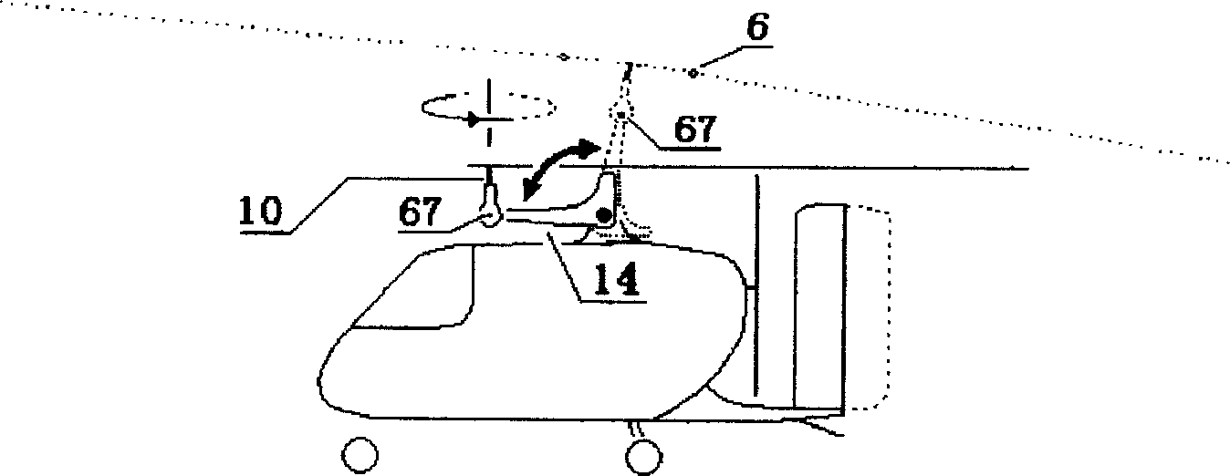
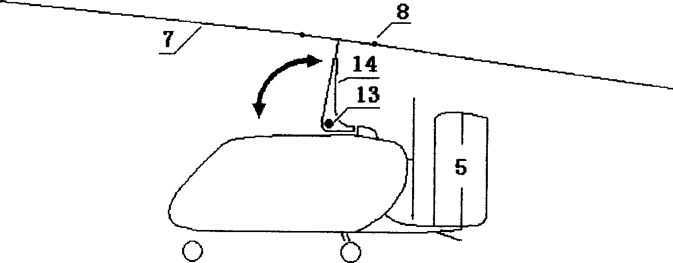
[0149] Figure 1 to Figure 8 , Figures 17, 18 and Figure 72 to Figure 7 Shown in 4, a kind of rotary wing flying car comprises parts such as fuselage, the power system of rotorcraft, horizontal propulsion drive propeller, empennage, landing gear, tilting storage type rotor strut 14 and folding rotor; Rotor strut 14 is erected and fixed Afterwards, the position of its installation, the backward inclination angle are identical with conventional rotorcraft, and the rotor that expands is autorotation rotor;

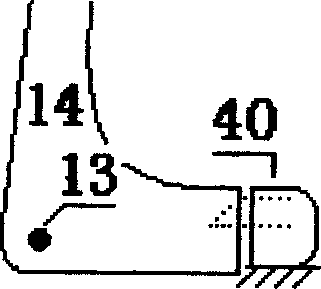
[0150] The lower end of the rotor prop 14 of the tilting storage type is connected with the top of the fuselage by the prop shaft 13, it can rotate to the longitudinal axis direction of the fuselage, tilt forward and store in a horizontal position; when its rotor prop 14 stands up, The prop positioning lock 40 that is fixedly installed on the fuselage can fix the rotor prop 14 and the fuselage together, and opening the prop positioning lock 40 can rotate the rotor prop 14 d...

Embodiment 2

[0153] Figure 125 As shown, the difference between this embodiment and "Embodiment One" is that the canopy 2 of this example can be opened forward, and the pilot can lean out from this, and the rotor at the upper end of the rotor strut 14 that is tilted forward is placed backward. Folding, other parts are the same as "Example 1".

Embodiment 3

[0155] The difference between this embodiment and "embodiment two" is that the canopy 2 of this example can be opened to the side, and the pilot can lean out from this, and the rotor at the upper end of the rotor strut 14 that is tilted and placed forward is folded backward, and other Part is the same as "Example 2".


PUM


Abstract

The invention relates to a kind of self-rotation rotaplane , whose rotor wing pillar 14 , rotor wing and tailspin is easy for folding collection and take up small ground space , thus it is a kind of rotor wing flying cars which is easy for takoff or landing on the road and maneuvering traveling . The plane adopts technology as inclined-spinning storing rotor wing pillar 14 , folding rotor wing and tailspin , light prewhirl drive , land traveling system , etc , thus its flying and traveling mobility and its safety performance are great . On the base of assuring self lighting and safety , the invention can take off and land in short distance , fold or unfold the wings swiftly , and well imitate the bird's mobility in remotely flying and short walking . Generally , in the range of ten kilometers from the destination , it is easy to find the place as road that is suitable for takoff and landing of the plane . The invention can take off or land from the location , traveling to the destination and get into the family garage , finish the nonstop traffic mission from point to point , thus it is really a new kind of aircraft that can get into the family .

Description

technical field [0001] The "rotor flying car" described in the present invention relates to a self-rotating rotor aircraft, which can be used for manned aircraft and models thereof, and is an improved invention to the existing rotor aircraft. Background technique [0002] A kind of rotorcraft of prior art, fuselage is bigger, and rotor strut is fixed above the fuselage, takes up a large space. It takes into account flight and ground maneuvering with the same engine, and the power cost of ground driving is high. It is difficult to match its high power, light body structure and vibration reduction for ground driving, and its practicability is poor, so it has not been mass-produced. [0003] Another kind of gyroplane of prior art, its rotor strut is fixedly installed on the fuselage top, and its long rotor and wide empennage take up a lot of space, can not be parked in common car garage, also does not possess road maneuvering Ability. [0004] The prior art helicopter has po...

Claims


Application Information

Patent Timeline
IPC IPC(8): B60F5/02
Inventor 章洪
Owner 章洪
Why Eureka
Try Eureka