
A signal control method for junction of entrance ramp and main trunk road

A technology of signal control and arterial road, which is applied in the traffic control system of road vehicles, traffic control system, traffic signal control, etc., to achieve the effect of low cost, wide range and avoiding traffic accidents

Inactive Publication Date: 2005-03-16
BEIJING JIAOTONG UNIV
View PDF0 Cites 21 Cited by
  • Summary
  • Abstract
  • Description
  • Claims
  • Application Information

AI Technical Summary

Problems solved by technology

[0004] In order to overcome the deficiency that existing control methods cannot solve the problem of conflicts between ramp vehicles and arterial vehicles, the present invention provides a signal control method at the junction of an entrance ramp and a main road, which can reduce the violent conflict between ramp vehicles and arterial vehicles , reduce the incidence of traffic accidents, and make full use of the traffic capacity of the main road

Method used


Image

  • A signal control method for junction of entrance ramp and main trunk road
  • A signal control method for junction of entrance ramp and main trunk road
  • A signal control method for junction of entrance ramp and main trunk road

Examples


Embodiment Construction

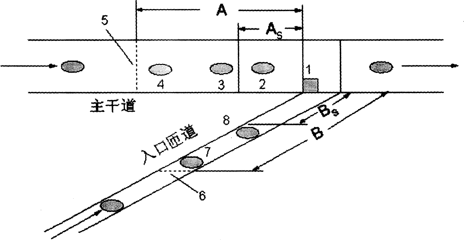
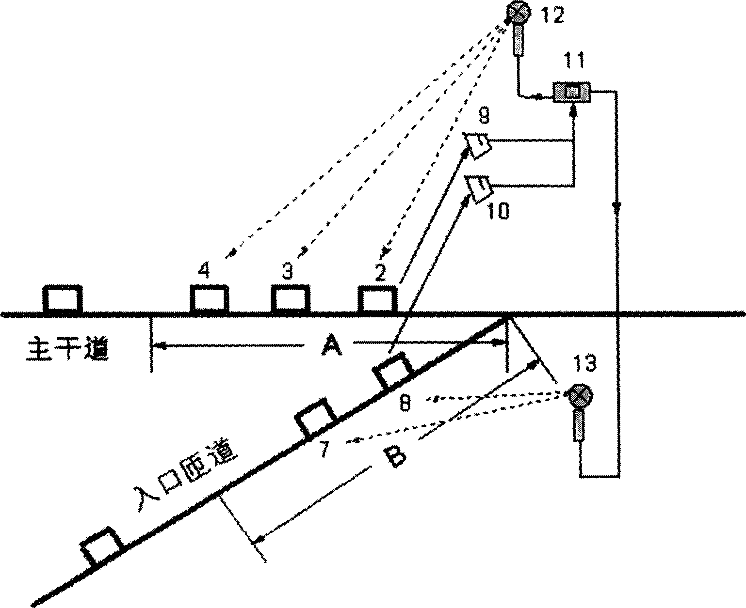
[0028] Embodiments of the present invention will be described in detail with reference to the accompanying drawings.

[0029] Such as figure 1 As shown in Fig. 1, signal point 1 is set at the confluence of the entrance ramp and the main road, and the main road control line 5 is set 60-80 meters upstream of the main road, and the area between the main road control line 5 and signal point 1 is the main road control Area A: The ramp control line 6 is set 60-80 meters upstream of the ramp, and the area between the ramp control line 6 and the signal point 1 is the ramp control area B. Install the control equipment at the signal point 1, including the main road distance measuring speedometer 9, the ramp distance measuring speedometer 10, the single chip microcomputer 11, the main road signal lamp 12, the ramp signal lamp 13, such as figure 2 shown. In the control process, the arterial road ranging speed measuring instrument 9 measures the position and the speed of the first car u...


PUM


Abstract

The invention relates to a method used to control the signal at the confluence of the entrance path and the arterial road. The arterial road distance and velocity finder (9) measures the position and velocity of the first vehicle at the upper position of the arterial road signal point (1) and delivers the data to the microcomputer (11). If the vehicle is located in the arterial road control area by the microcomputer and the vehicle velocity is faster than the maximum limiting speed, the signal light (13) of the by path is controlled to deliver the speed limiting signal to the vehicles (7),(8) in the by path control area. The bypath distance and velocity finder (10) measures the position and velocity of the first vehicle at the upper position of the by path signal point (1) and delivers the data to the microcomputer (11). If the vehicle is located in the by path control area by the microcomputer and the vehicle velocity is faster than the maximum limiting speed, the arterial road signal light (12) is controlled to deliver the speed limiting signal to the vehicles (2),(3),(4) in the arterial road control area. This control method decreases the cross collision between the vehicle of the bypath and the arterial road. The traffic accident rate can be reduced and the arterial road capacity can be of full utilization.

Description

technical field [0001] The invention relates to a signal control method of an entrance ramp system in highway traffic. Background technique [0002] The signal control method of the on-ramp system in the existing highway traffic is described in "Intelligent Traffic Control Theory and Its Application", Liu Zhiyong, Science Press, 2003, and there are timing control and traffic induction control. The timing control method is to set a fixed ramp flow regulation law based on historical traffic data, which is stable but cannot adapt to changes in traffic flow. The traffic induction control method is to dynamically detect the traffic demand of the upstream arterial road and the traffic capacity of the downstream arterial road, and then determine the ramp adjustment rate according to the difference, which can adapt to the real-time changes of traffic flow, but the vehicles on the ramp will merge into the main road. Conflicts with vehicles on the main road are prone to safety hazard...

Claims


Application Information

Patent Timeline
IPC IPC(8): G08G1/00G08G1/08
Inventor 高自友贾斌李克平
Owner BEIJING JIAOTONG UNIV
Learn More