
Liquid crystal display device

A liquid crystal display device and liquid crystal panel technology, which is applied to static indicators, light guides, optics, etc., can solve problems such as reducing the display screen of liquid crystal panels, and achieve the effects of improving assembly work efficiency, preventing wrinkles, and increasing the display screen.

Active Publication Date: 2005-03-23
JAPAN DISPLAY INC
View PDF2 Cites 11 Cited by
  • Summary
  • Abstract
  • Description
  • Claims
  • Application Information

AI Technical Summary

Problems solved by technology

Therefore, the display screen of the liquid crystal panel has to be reduced substantially.

Method used


Image

  • Liquid crystal display device
  • Liquid crystal display device
  • Liquid crystal display device

Examples


Embodiment Construction

[0040] Hereinafter, the best mode for carrying out the present invention will be described with reference to the drawings. However, the embodiments described below are examples of liquid crystal display devices that embody the technical idea of ​​the present invention, and are not intended to limit the present invention to such liquid crystal display devices, and are similarly applicable to other embodiments included in the claims. way of liquid crystal display devices.

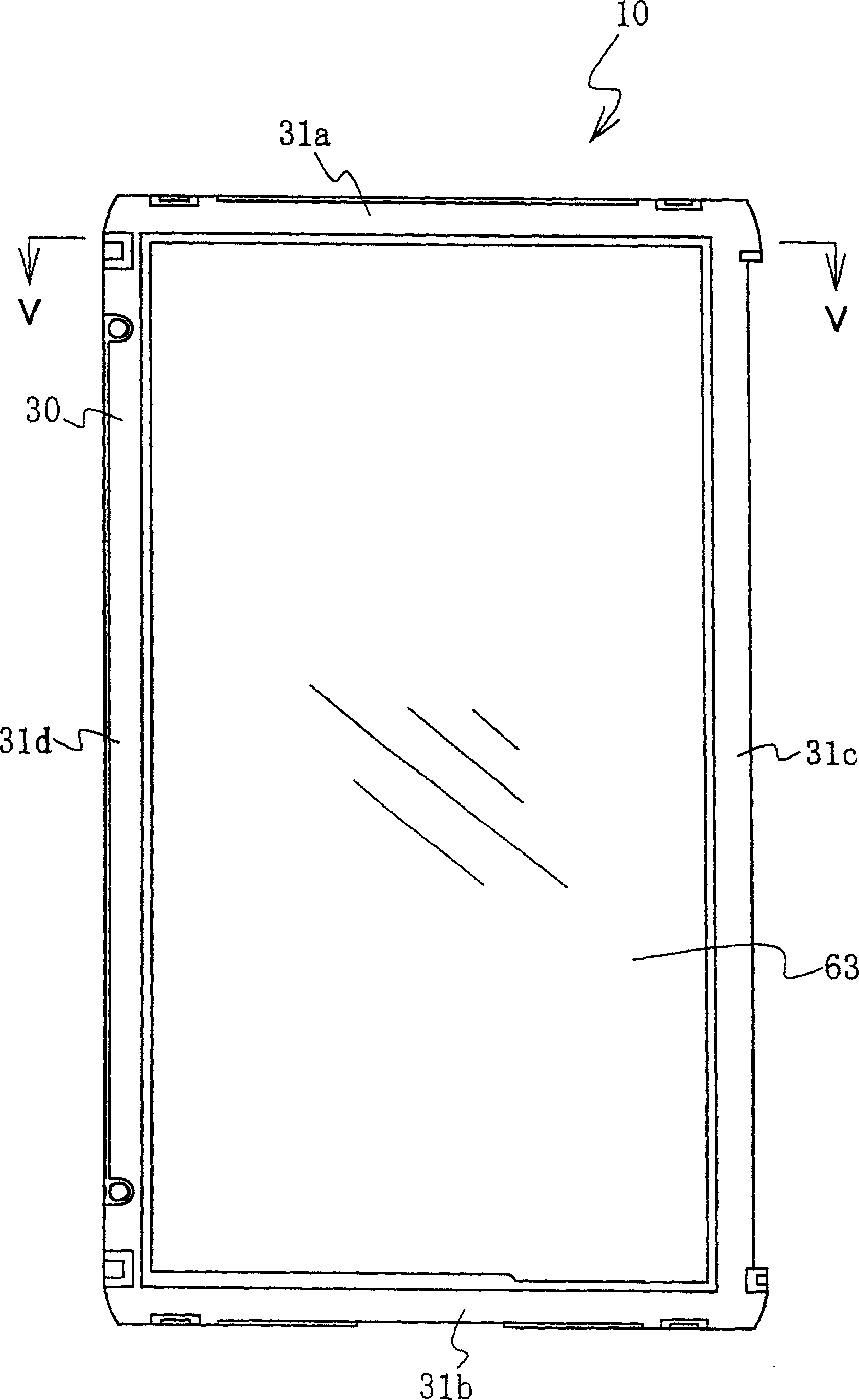
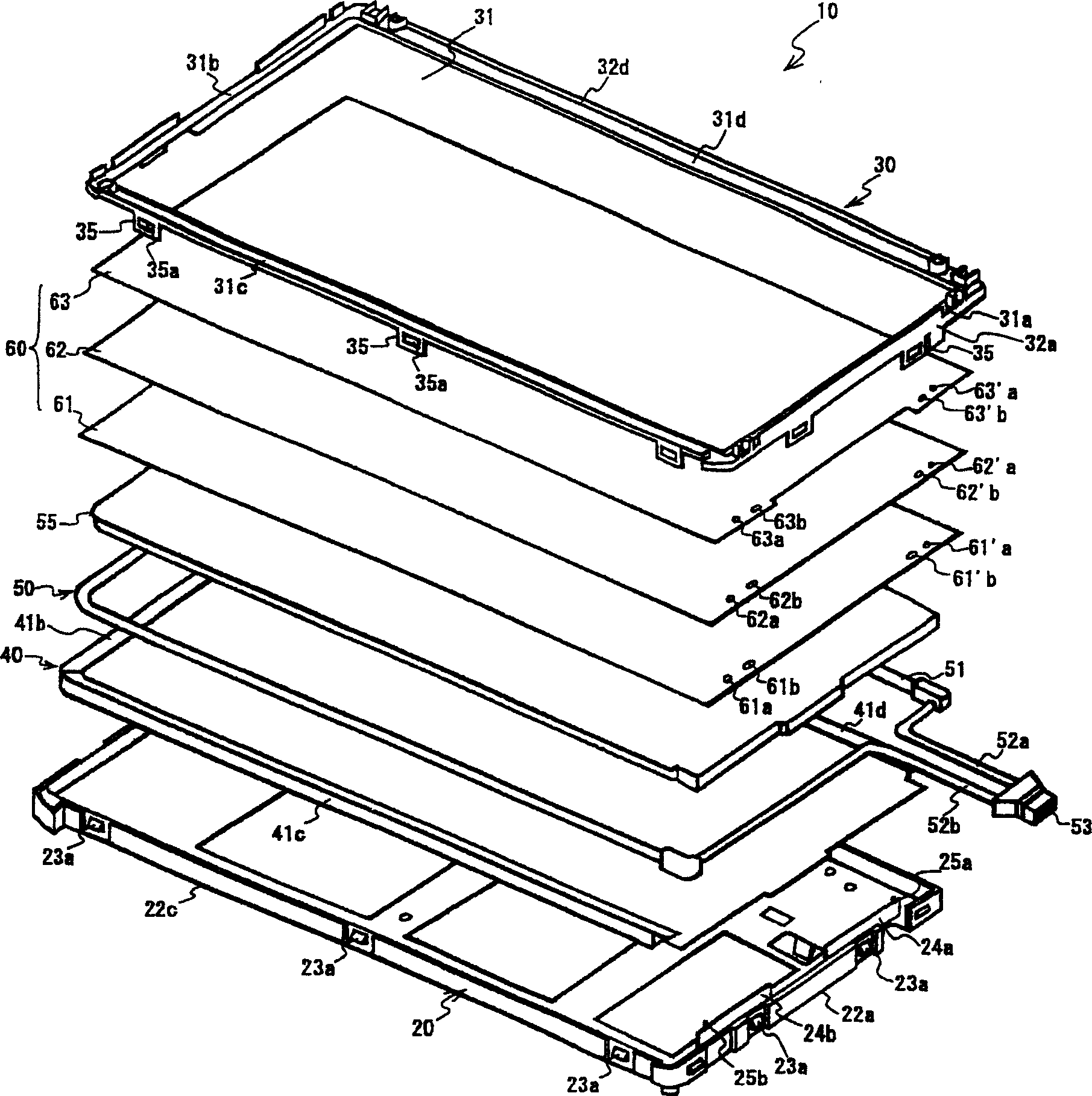
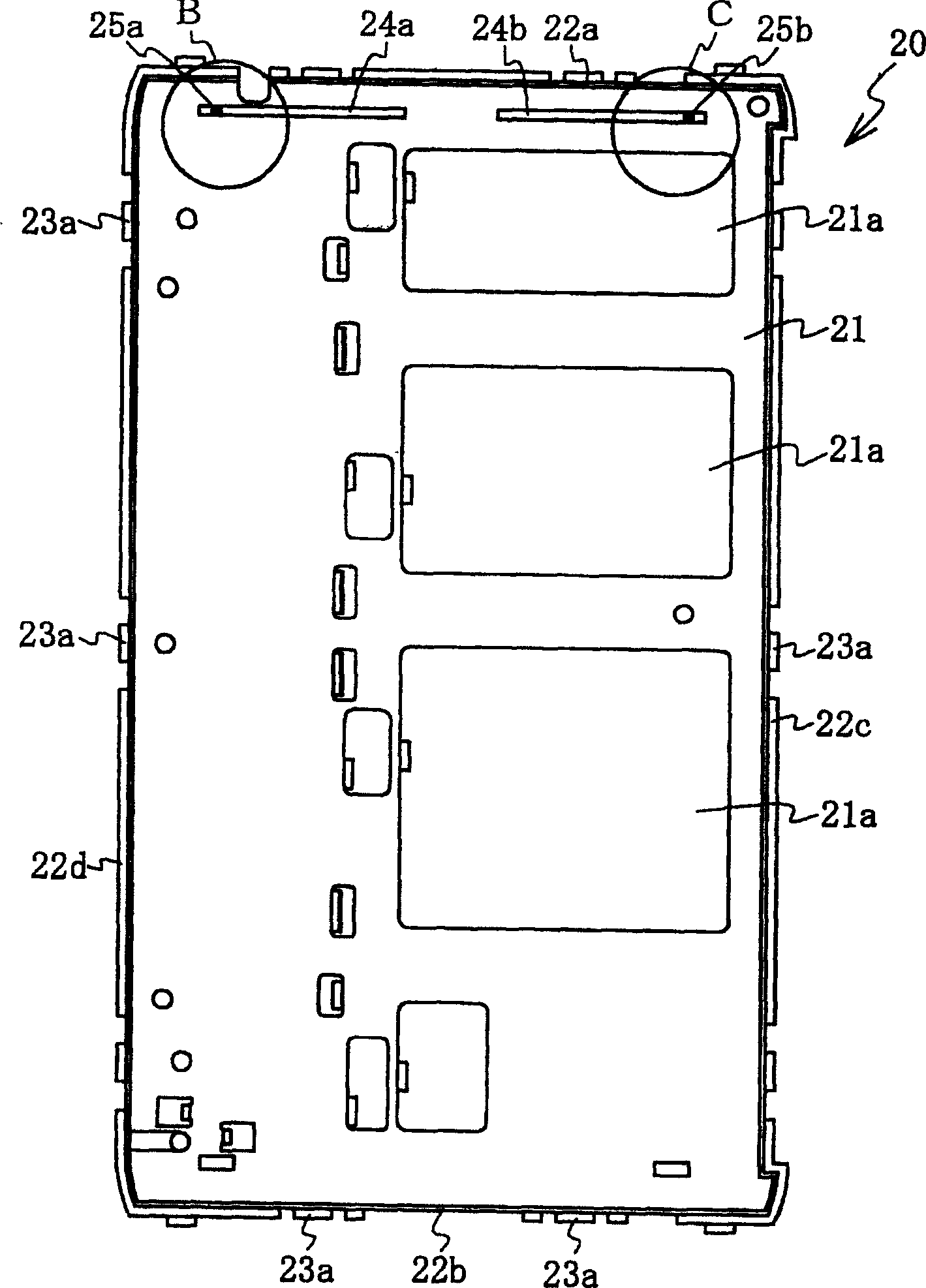
[0041] Liquid crystal display device 10, such as figure 2 As shown, it includes: a light source 50; a flat light guide plate 55 that transmits light from the light source 50; a reflective sheet 40 configured along the back of the light guide plate 55; an optical sheet 60 placed on the light guide plate 55. The laminate composed of these components is inserted between the main frame 20 and the sub-frame 30, and the sub-frame 30 is installed on the main frame 20, thereby positioning and fixing the aforementio...


PUM


Abstract

A liquid crystal display device (10) includes a liquid crystal panel, at least one optical sheet (60) substantially rectangular in shape, where first (61a,62a,63a,61'a,62'a,63'a) and second (61b,62b,63b,61'b,62'b,63'b) openings are formed at the opposite ends of one side of the optical sheet at a predetermined interval, a main frame (20) in which the optical sheet(s) are placed, and a sub-frame (30) arranged above the optical sheets and the main frame, in which the main frame is provided with first small protrusions (25a,25b) jutting upward corresponding to the first openings at the top surface, while the rear surface of the sub-frame is provided with second small protrusions (33a,33b) jutting downward corresponding to the second openings, thereupon the first small protrusions are inserted into the first openings of the optical sheet(s) and the second small protrusions are inserted into the second openings to connect and install the sub-frame to the main frame, and the optical sheet(s) are then aligned and fixed. Accordingly, the optical sheets are aligned better and firmly fixed to achieve larger display screens and thinner liquid crystal display devices and wrinkles are prevented from occurring in the optical sheets.

Description

technical field [0001] The present invention relates to a liquid crystal display device, in more detail, relates to a liquid crystal display device which improves the positioning and fixing of optical sheets, and realizes the enlargement of the display screen and the thinning of the device. Background technique [0002] Conventional liquid crystal display devices generally have a plurality of optical sheets inserted between the light guide plate and the liquid crystal panel, and these optical sheets are usually fixed to the main frame with double-sided tape. [0003] However, when the liquid crystal panel moves or an impact is applied to the liquid crystal display device from the outside, since the optical sheet is fixed with double-sided tape, the stretching and movement of the optical sheet becomes difficult, causing wrinkles and damage. In addition, there is a problem that the work of affixing the double-sided tape to the optical sheet or the like is cumbersome and poor i...

Claims


Application Information

Patent Timeline
Patent Type & Authority Applications(China)
IPC IPC(8): G02F1/1333G02F1/13G02F1/13357
CPCG02B6/0088G02F1/133615G02F1/133308G02B6/0085G02F2001/133317G02F2201/54G02F1/133317G02F1/1333
Inventor 早野聪
Owner JAPAN DISPLAY INC
Learn More