
Rotating axle of induction motor

A technology for induction motors and rotating shafts, applied in the direction of electric components, shafts, electrical components, etc., can solve the problems of poor bearing position, increase the number of parts, and maintain bearings, so as to prevent poor position and reduce the number of parts Effect

Inactive Publication Date: 2005-03-30
LG ELECTRONICS (TIANJIN) APPLIANCES CO LTD
View PDF0 Cites 1 Cited by
  • Summary
  • Abstract
  • Description
  • Claims
  • Application Information

AI Technical Summary

Problems solved by technology

[0006] However, the rotor of the existing induction motor as described above has the following disadvantages: in order to maintain the distance between the bearings, a concave connecting groove (22) is formed along the radial direction on the rotating shaft (21), and the connecting groove (22) Upper connection brake ring(23)
This increases the number of parts and complicates the assembly process, leading to higher costs
Sometimes, because the brake ring (23) is not fully inserted, it is easy to make the brake ring (23) detached from the rotating shaft (21), so that the position of the bearing (19) is not good

Method used


Image

  • Rotating axle of induction motor
  • Rotating axle of induction motor
  • Rotating axle of induction motor

Examples


Embodiment Construction

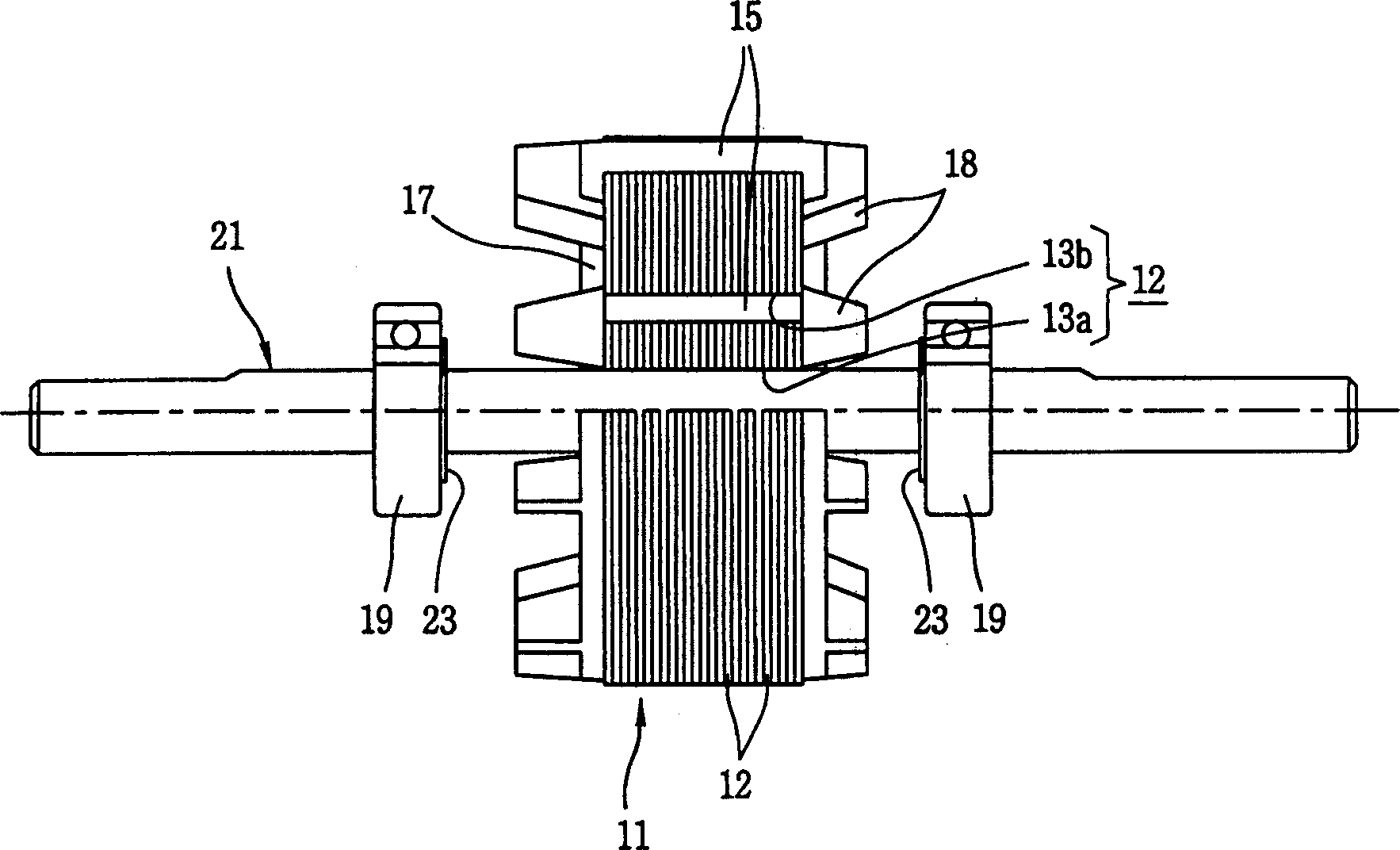
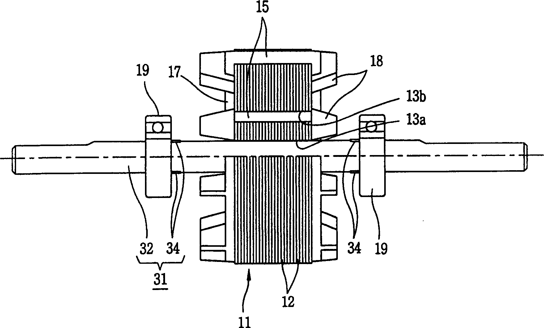
[0026] like image 3 , Figure 4 , Figure 5 , Image 6 , Figure 7 As shown, the induction motor of the present invention includes a rotor core (11), a conductor bar (15), a locking (end ring) (17), and a rotating shaft (31). The above-mentioned rotor iron core (11) is formed by several silicon steel plates (12) insulated and laminated, and the silicon steel plate (12) has a shaft hole (13a) and several slots (13b), and each slot of the rotor iron core (11) ( 13b) Conductor rods (15) are formed inside; locking rings (17) are respectively provided at both ends of the rotor iron core (11), and the axis of the rotor iron core (11) is combined with the rotating shaft (31) of the induction motor of the present invention.

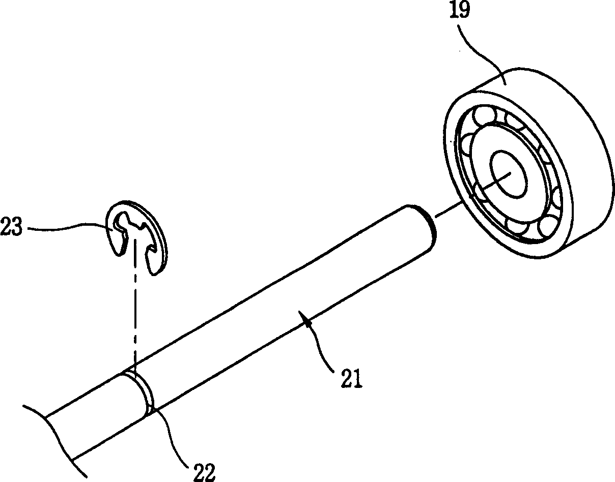
[0027] The rotating shaft (31) of the induction motor of the present invention includes a rotating shaft body (32) and a bearing stopper (stopper) (34). (11) Insert the rotor core (11) integrally; the bearing locking device (34) is integrally formed with th...


PUM


Abstract

Rotation axis includes following parts: body of rotation axis in round bar shape, the body of rotation axis together with axes of rotor iron core as a integral part is connected to rotor iron core; bearing blocking device is extruded out body of rotation axis along radius direction, forming a integrated body with the body of rotation axis in order to prevent bearings from closing each other; bearings along length direction of the body of rotation axis are combined on two sides of the iron core of rotor. Advantages are: brake ring not utilized for fixing position of bearings so as to reduce quantity of parts and preventing bearings from not suitable position.

Description

technical field [0001] The present invention relates to a rotating shaft of an induction motor. Background technique [0002] figure 1 is a schematic diagram of an existing induction motor rotor, figure 2 Yes figure 1 An exploded perspective view of the bearing section shown. As shown in the figure, the rotor of the induction motor includes a rotor core (11) and a rotating shaft (21). The above-mentioned rotor iron core (11) is arranged in a certain space inside the stator not shown in the figure, and the rotor iron core (11) can rotate; a rotating shaft (21) is combined along the axis of the rotor iron core (11), The rotating shaft (21) rotates together with the rotor core (11). [0003] The rotor core (11) includes a shaft hole (13a), a silicon steel plate (12), a conductor bar (15), and a locking ring (end ring) (17). The above-mentioned shaft hole (13a) is formed through the center of the rotor core (11), and the rotating shaft (21) is installed inside; several sl...

Claims


Application Information

Patent Timeline
IPC IPC(8): F16C3/02H02K7/08
Inventor 李忠一
Owner LG ELECTRONICS (TIANJIN) APPLIANCES CO LTD
Features
  • Generate Ideas
  • Intellectual Property
  • Life Sciences
  • Materials
  • Tech Scout
  • Unparalleled Data Quality
  • Higher Quality Content
  • 60% Fewer Hallucinations
Learn More