Virtual time slot exchange method and its application circuit

A time slot switching and delay circuit technology, applied in time division multiplexing systems, time division multiplexing selection devices, electrical components, etc., to simplify complex logic, reduce PCB wiring area, and save time slot switching chips Effect

Active Publication Date: 2010-10-20
MAIPU COMM TECH CO LTD
View PDF2 Cites 0 Cited by
  • Summary
  • Abstract
  • Description
  • Claims
  • Application Information

AI Technical Summary

Problems solved by technology

[0004] The technical problem to be solved by the present invention is to provide a virtual time slot exchange method and implementation circuit for the disadvantages of high cost of time slot exchange chips and complicated wiring

Method used


Image

  • Virtual time slot exchange method and its application circuit
  • Virtual time slot exchange method and its application circuit
  • Virtual time slot exchange method and its application circuit

Examples


Embodiment 1

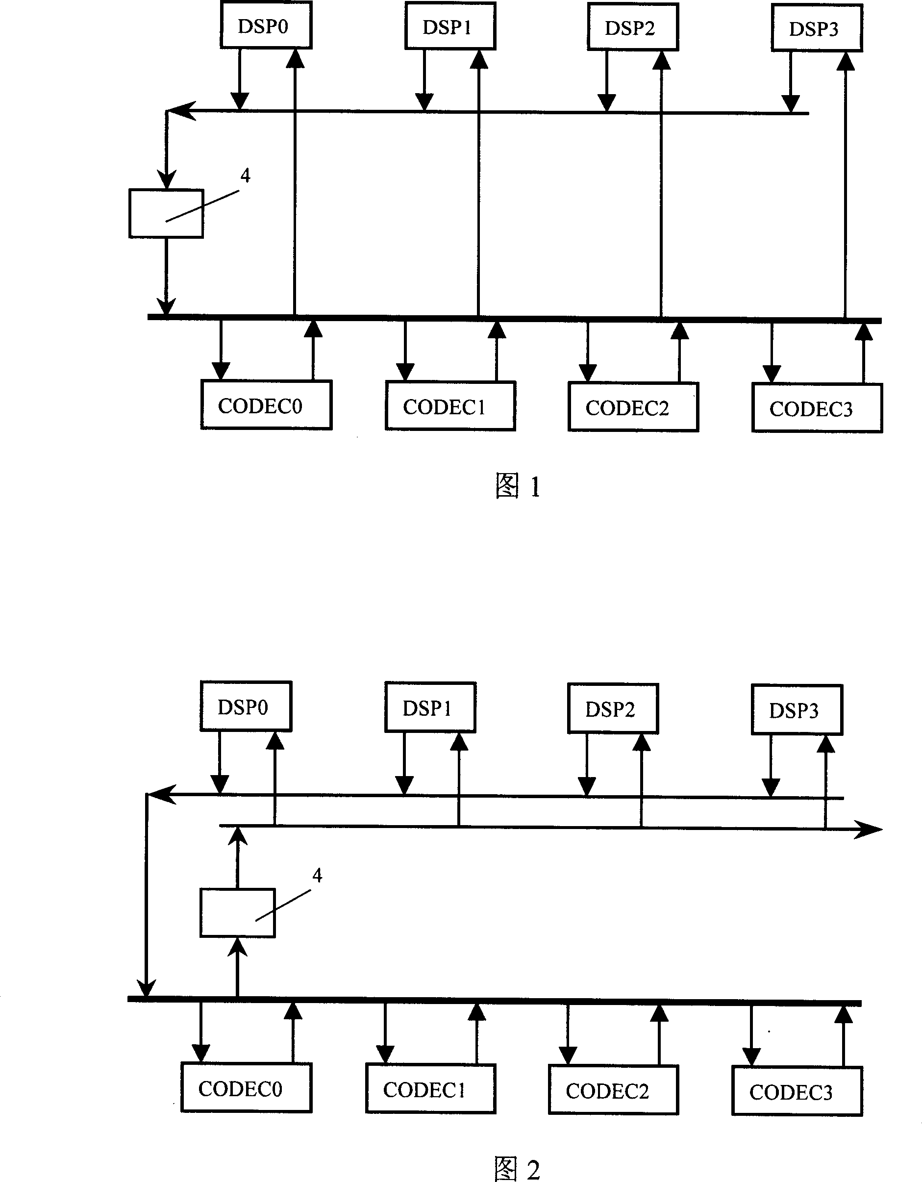
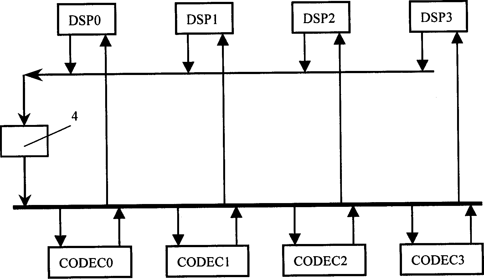
[0026] figure 1 It shows a schematic diagram of shifting the DSP transmission time slot by 1 time slot.

[0027] First of all, all DSPs in the system will not send data in the same time slot, and when the DSP is not sending data, its transmission line is in a high-impedance state, so the transmission lines of all DSPs can be connected in parallel, and then through an 8bit shift register 4 Access to the TDM bus. The effect of 8bit shift register 4 on this sending bus is to delay the data sent by DSP by 1 time slot. Assuming that the receiving time slot number of DSP0 is n, its corresponding sending time slot number is equivalent to n +1.

[0028] In the second step, usually the CODEC's sending and receiving time slot numbers can be configured independently, and the following points should be noted at the same time:

[0029] All CODECs will not send data in the same time slot;

[0030] When the CODEC does not send data, the sending line is high impedance;

[0031] The rece...

Embodiment 2

[0052] The shift register 4 in this example is connected to the receiving end of the DSP, and the effect produced is to move the receiving time slot of the DSP by one time slot. If the DSP transmits time slot is n, its receiving time slot is equivalent to n+1. The method for exchanging virtual time slots in this example is similar to that in Embodiment 1 and will not be repeated here. schematic diagram see figure 2 .

Embodiment 3

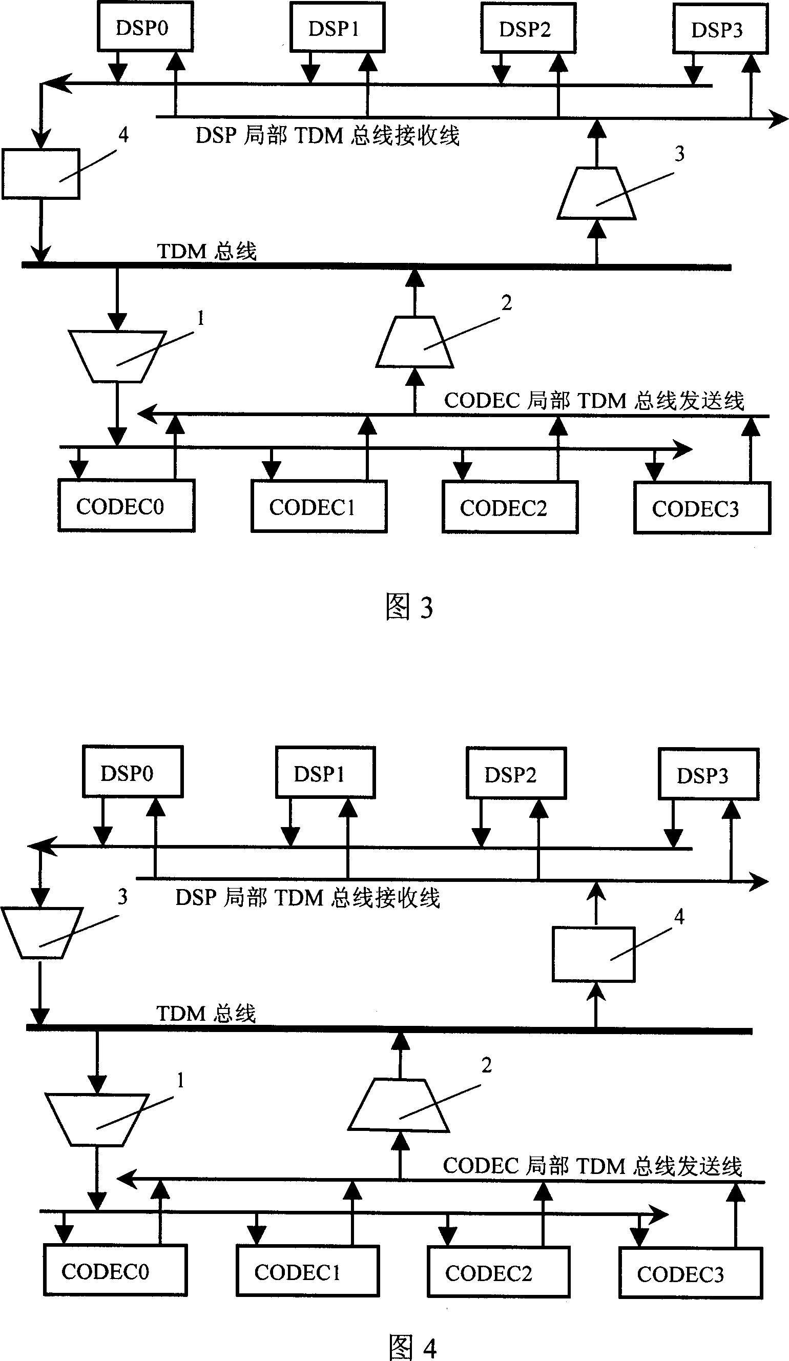
[0054] Considering the load capacity of the device, the hardware connection relationship of the implementation circuit is as follows: image 3 . In this case in figure 1 Based on the addition of 3 bus drivers. The bus driver 1 is connected between the receiving line of the CODEC local TDM bus and the TDM bus to solve the load capacity of the shift register 4. The bus driver 2 is connected between the CODEC local TDM bus sending line and the TDM bus to solve the load capacity of the CODEC. The driver 3 is connected between the DSP local TDM bus receiving line and the TDM bus, and is used to drive multiple DSPs, reducing the load of the bus driver 1 and the bus driver 2 . If the number of DSP and CODEC is not much, you can also follow figure 1 implement.


PUM


Abstract

The invention solves issues of high cost of time slot exchange chip and complex wiring. The technical scheme contains DSP and CODEC for receiving data through TDM bus, including steps: (a) time delay circuit is cascaded in TDM bus, thus, time slot received by DSP is delayed and staggered in k pieces of time slots; (b) configuring sending time slot and receiving time slot of CODEC in order to correspond to receiving and sending time slots. The implementing circuits include TDM bus, DSP, and CODEC. DSP through delay circuit is connected to TDM bus. The invention simulates function of time slot exchange chip in virtual mode, and realizes communication connection between CODECs and between CODEC and DSP. The invention is suitable to time slot exchange in small type IP telephone gateway and PBX system etc.

Description

technical field [0001] The invention relates to time-division multiplexing technology, in particular to a time slot exchange method and a system circuit. Background technique [0002] In digital program-controlled switches and similar devices, communication endpoints can be connected through hardware connection, multi-way switch, time slot exchange, etc., especially voice data, usually using TDM (time division multiplexing) bus transmission. When the TDM bus is used to transmit data, the communication endpoints can exchange data on the designated time slot of the TDM bus. When the density is low, the method of fixed time slot can be used to exchange data. When the density is high, the connection between the endpoints The relationship is complex, and time slot switching chips are usually used to exchange data. [0003] In systems such as IP telephone gateways and digital PBXs (public telephone program-controlled exchanges), there are generally several CODECs (voice codecs)...

Claims


Application Information

Patent Timeline
Patent Type & Authority Patents(China)
IPC IPC(8): H04J3/00H04Q11/04
Inventor 任震宇邓刚王锋茂
Owner MAIPU COMM TECH CO LTD
Why Eureka
Try Eureka