Method for realizing short gauge jumping rail through employing step motor

A stepping motor and short track technology, which is applied in the field of controlling the stepping motor, can solve the problems of sacrificing the performance of the optical disc drive, low optical signal quality, slowing down, etc.

Inactive Publication Date: 2005-04-13
MEDIATEK INC
View PDF0 Cites 4 Cited by
  • Summary
  • Abstract
  • Description
  • Claims
  • Application Information

AI Technical Summary

Problems solved by technology

This method of using the servo feedback control of the pulley 15, under the limitation of the slow dynamic characteristics of the pulley 15, will cause a decrease in system stability and a decrease in the quality of the optical signal
If want to solve the problem of above-mentio

Method used


Image

  • Method for realizing short gauge jumping rail through employing step motor
  • Method for realizing short gauge jumping rail through employing step motor
  • Method for realizing short gauge jumping rail through employing step motor

Examples


Embodiment Construction

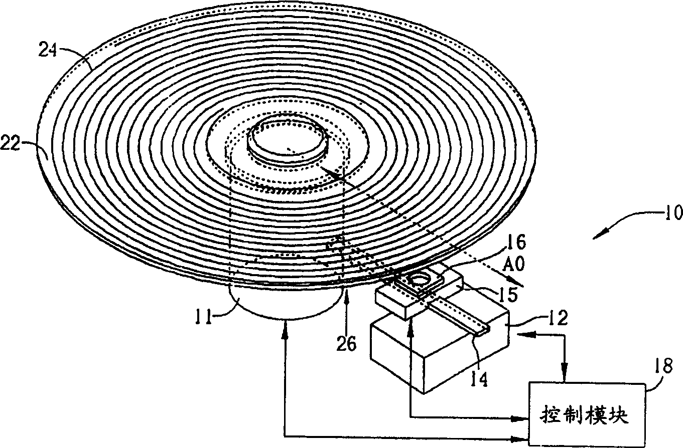
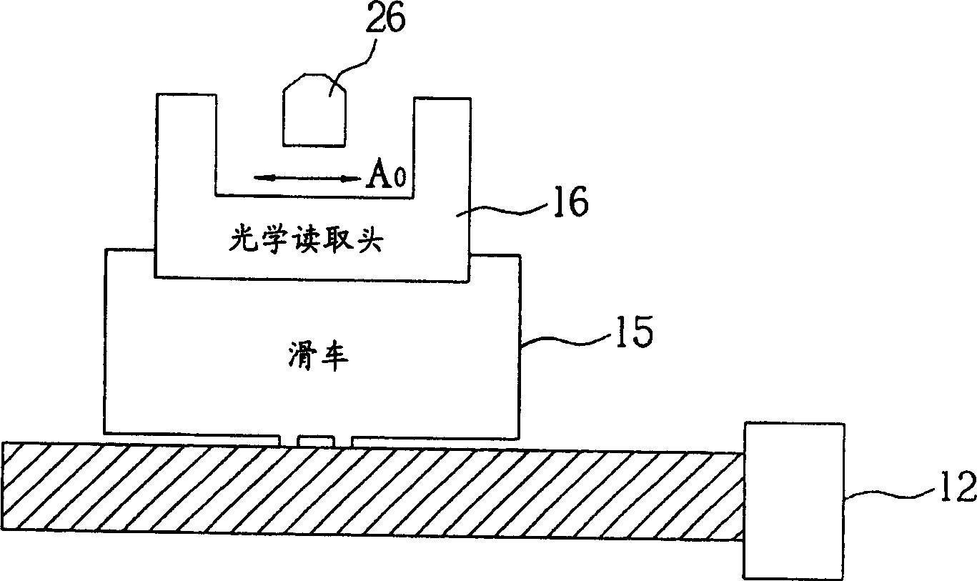
[0026] Firstly, the technical feature of the present invention is based on the use of a stepping motor, and uses the stepping motor to drive a pulley and an optical reading head to achieve the effect of pre-driving and precise positioning. Stepping motors are widely used in industry, and have been gradually popularized in the application of microcomputer peripheral equipment. Generally speaking, a stepping motor operates in a stepping manner. As long as a square wave signal is input, the stepping motor can determine the angle of rotation according to the amount of the square wave signal. When there is no square wave signal, the stepping motor maintains a static state, and when a continuous square wave is given, the stepping motor rotates continuously at a fixed angle. In this way, the stepping motor can perform instant start and rapid stop, and can achieve precise position control. Generally, the stepping motor 32 rotates a relatively large distance, so the general optical di...


PUM


Abstract

The invention provides a method for controlling stepped motor in a track jumping operation for short track width in an optical storage system, wherein the optical storage system also includes an optical reading head and an object lens group, the method comprises calculating the number of steps wherein the step motor rotation is one, moving the object lens group to a target trajectory, using the step motor to move the optical reading head to a destination location.

Description

technical field [0001] The present invention provides a method for controlling a stepping motor in an optical storage system, in particular to a method for controlling the stepping motor in the optical storage system to realize a short track jump operation method. Background technique [0002] In today's various optical storage systems, when users want to read data on an optical disc (Optical Disc) or want to write to the optical disc, they must use an optical pickup head (Pick -Up Head) to the target track (Target Track) on the disc for data reading or writing operations. In the following embodiments, an optical disc drive is taken as an example to illustrate the situation when the optical disc drive performs data access operations and the related transmission system. see figure 1 , figure 1 is a schematic diagram of a typical optical disc drive 10 . The optical disk drive 10 includes a spindle motor (spindle motor) 11 fixed in the optical disk drive, a carriage motor ...

Claims


Application Information

Patent Timeline
IPC IPC(8): G11B7/00G11B7/005G11B7/1374G11B21/02
Inventor 黄佳凌
Owner MEDIATEK INC
Why Eureka
Try Eureka