Reinforcement and cooling structure of a turbine blade

A technology of turbine blades and blades, which is applied in the direction of blade support components, stators, engine components, etc., can solve the problems of reduced overall efficiency and cooling efficiency, and achieve high overall efficiency, high cooling efficiency, and good heat exchange.

Inactive Publication Date: 2005-04-13
SIEMENS AG
View PDF1 Cites 2 Cited by
  • Summary
  • Abstract
  • Description
  • Claims
  • Application Information

AI Technical Summary

Problems solved by technology

However, due to the increase in wall thickness, the cooling efficiency is reduced and the overall efficiency is thus reduced

Method used


Image

  • Reinforcement and cooling structure of a turbine blade
  • Reinforcement and cooling structure of a turbine blade
  • Reinforcement and cooling structure of a turbine blade

Examples


Embodiment Construction

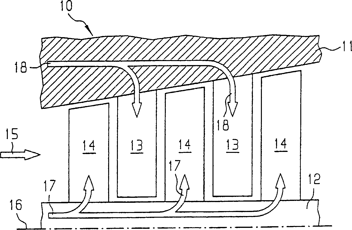
[0028] figure 1 A longitudinal sectional view of a turbine shown as a turbine 10 with a casing 11 and a rotor 12 . The housing 11 is provided with guide vanes 13 and the rotor 12 is provided with rotor blades 14 . In operation, fluid flows through turbine 10 in direction of arrow 15 , the fluid flows along guide vanes 13 and rotor blades 14 , causing rotor 12 to begin rotating about centerline 16 .

[0029] In most applications, the temperature of the fluid is high, especially in the region of the first row of blades ( figure 1 shown in the center left). For this purpose, the guide blades 13 and the rotor blades 14 are cooled. The flow of cooling fluid is schematically indicated by arrows 17 , 18 . In particular air can be used as cooling fluid.

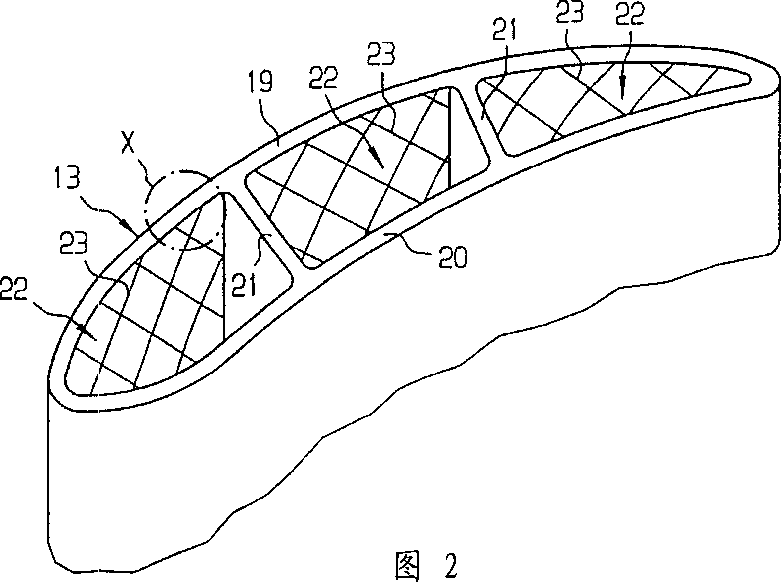
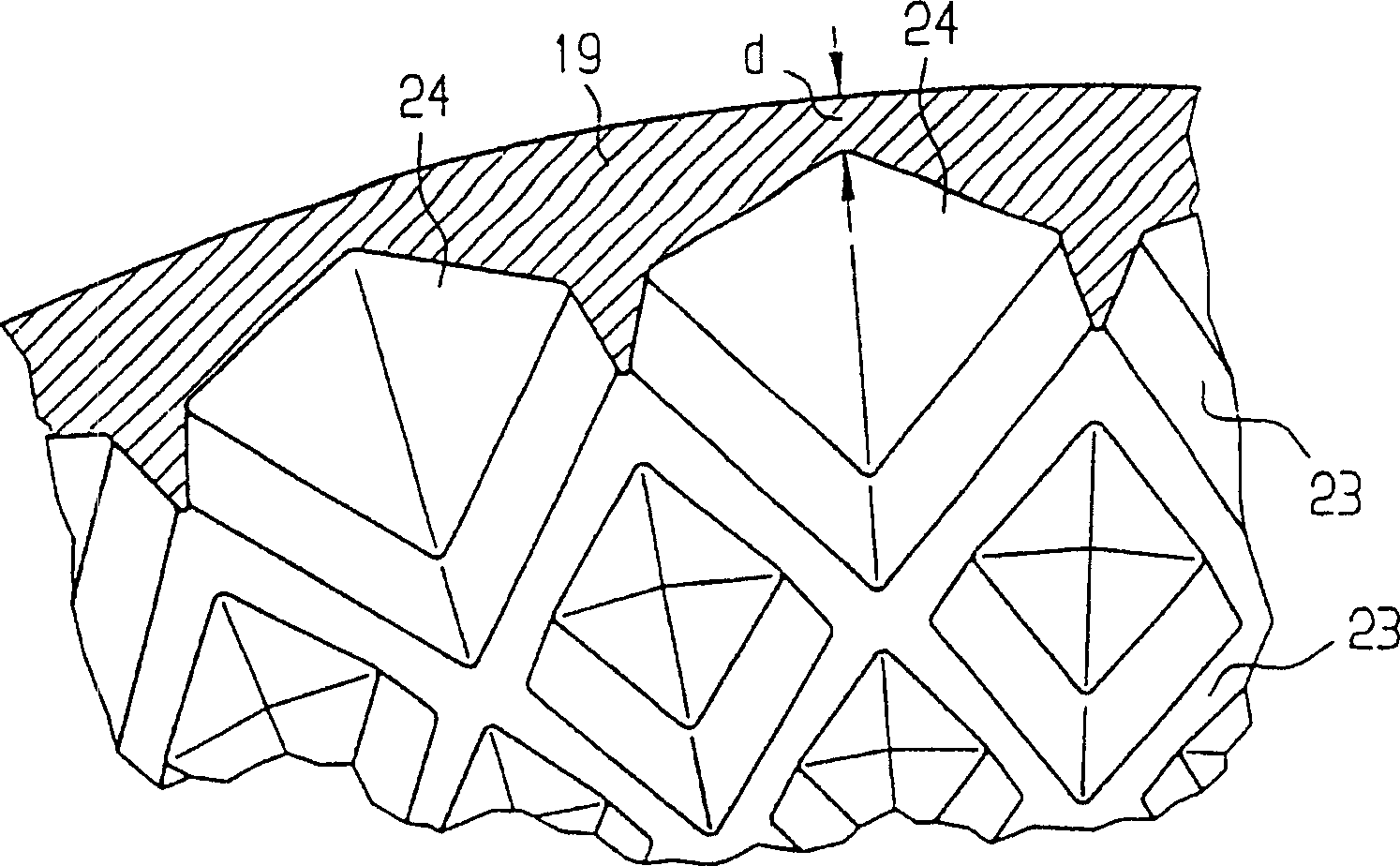
[0030] FIG. 2 schematically shows an exploded view of the guide vane 13 . The guide vanes 13 have curved outer walls 19 , 20 . The interior space between the outer walls 19 , 20 is subdivided by means of two partition walls 21...


PUM


Abstract

The invention discloses a blade (13; 14) for a turbine (10) having at least one duct (22) which can be impinged by a cooling fluid. Several turbulators (23) for improving the heat exchange between the wall (19; 20) and the cooling fluid are arranged on at least one wall (19; 20) of the delivery pipe (22). Furthermore, turbulators (23) reinforce the walls (19; 20) and converge. As a result of said strengthening, the thickness (d) of the walls (19; 20) in the region between the turbulators (23) can be reduced.

Description

technical field [0001] The invention relates to a blade, in particular a turbine blade, having at least one duct defined by a plurality of walls into which a cooling fluid can be introduced, a plurality of turbulators being arranged on at least one of the walls in order to increase the distance between the wall and the cooling fluid. heat exchange between them. Background technique [0002] Such a turbine blade is known from eg EP0758932B1. The known turbine blade is hollow and has four ducts. Each delivery pipe is respectively defined by the two outer walls of the turbine blade and separate walls, and the cooling fluid flows through each delivery pipe for cooling use. The outer walls are provided with turbulators to enhance heat exchange between the outer walls and the cooling fluid. [0003] In known turbine blades, turbulators are only used to improve heat exchange. The loads on the turbine blades that occur during operation are absorbed almost entirely by the outer w...

Claims


Application Information

Patent Timeline
Patent Type & Authority Applications(China)
IPC IPC(8): F01D5/14F01D5/18F01D9/02
CPCF01D5/147F01D5/187F05D2250/28F05D2260/2212F05D2260/22141
Inventor 汉斯-托马斯·博尔姆斯彼得·蒂曼
Owner SIEMENS AG
Why Eureka
Try Eureka