

Gateway system
A gateway and short packet technology, which is applied in the field of gateway systems, can solve the problems of inability to judge the loss of short packets and difficult to maintain call quality, etc.
- Summary
- Abstract
- Description
- Claims
- Application Information
AI Technical Summary
Problems solved by technology
Method used
Image

Examples
Embodiment 1
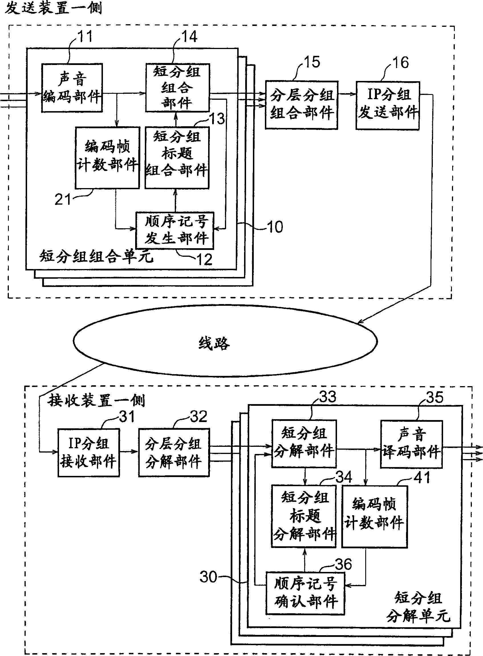
[0020] figure 1 It is a configuration diagram showing a gateway system according to Embodiment 1 of the present invention. exist figure 1 Among them, the short packet combination unit 10 is a device that converts input audio into encoded frames to generate payload data, and on the other hand, generates sequence signals and combines short packet headers to assemble short packets. The audio coding unit 11 performs audio coding processing of the audio signal, and outputs the encoded audio signal. The encoded frame counting section 21 counts the number of frames (encoded frames) of the encoded audio signal output from the audio encoding section 11, and outputs the counted number. The sequence mark generating unit 12 generates a sequence mark based on the count number output by the encoded frame counting unit 21 . The short packet header combination unit 13 generates a short packet header based on the sequence code generated by the sequence code generation portion 12 and outputs...
Embodiment 2
[0032] Figure 4 It is a configuration diagram showing a gateway system according to Embodiment 2 of the present invention. exist Figure 4 Among them, the audio coding type determination section 22 outputs to the order mark generation section 12 the type of the audio coding method used when the audio coding section 11 encodes the input audio signal. The audio coding type determining unit 42 determines the audio encoding type based on the order code extracted from the short packet header by the short packet header decomposing unit 34, and outputs the audio encoding type information to the audio decoding unit 35. Furthermore, in Figure 4 In , the same components as those in Embodiment 1 are denoted by the same symbols, and description thereof will be omitted.
[0033]The related operations are described below. The audio encoding unit 11 performs audio encoding processing on the input audio signal, and outputs the encoded audio signal as a result of the processing to the sh...
Embodiment 3
[0041] Figure 6 It is a configuration diagram showing a gateway system according to Embodiment 3 of the present invention. Example 3 is a combination of Example 1 and Example 2, and the same components are denoted by the same symbols, and descriptions thereof are omitted.
[0042] The related operations are described below. The audio encoding section 11 performs audio encoding processing on the input audio signal, and outputs the encoded audio signal as a result of the processing to the short packet combining section 14, the encoded frame counting section 21, and the audio encoding type determining section 22. The encoded frame counting section 21 counts the number of encoded frames of the encoded audio signal, and outputs the count to the sequence mark generating section 12 . The audio coding type determining unit 22 determines the type of the audio encoding method used in the audio encoding process based on the information from the audio encoding unit 11, and outputs the ...
PUM
 Abstract
Description
Claims
Application Information