Method for manufacturing motor stator

A manufacturing method and technology for motor stators, which are applied in the manufacture of motor generators, stator/rotor bodies, electrical components, etc., can solve problems such as difficulty in winding operation and motor constraints, and achieve the effect of convenient winding operation and improved efficiency.

Inactive Publication Date: 2005-05-04
LG ELECTRONICS (TIANJIN) APPLIANCES CO LTD
View PDF0 Cites 0 Cited by
  • Summary
  • Abstract
  • Description
  • Claims
  • Application Information

AI Technical Summary

Problems solved by technology

[0005] However, the prior art has the following problem: since the winding needle needs to be moved around the outer ring of the tooth 16 in the axial direction through the slit 14 during the winding operation, the winding needle needs to be wound on each tooth 16. A winding space G capable of moving the above-mentioned winding needles needs to be reserved between the coils 19
As a result, coils 19 cannot be wound as much as possible on the above-mentioned teeth 16, and therefore the performance of the motor can be improved to a certain extent.
In addition, the winding needle will be hindered by the coil 19 wound on the adjacent tooth 16, thus making the winding operation difficult.

Method used


Image

  • Method for manufacturing motor stator
  • Method for manufacturing motor stator
  • Method for manufacturing motor stator

Examples


Embodiment Construction

[0017] Embodiments of the present invention will be described in detail below with reference to the accompanying drawings.

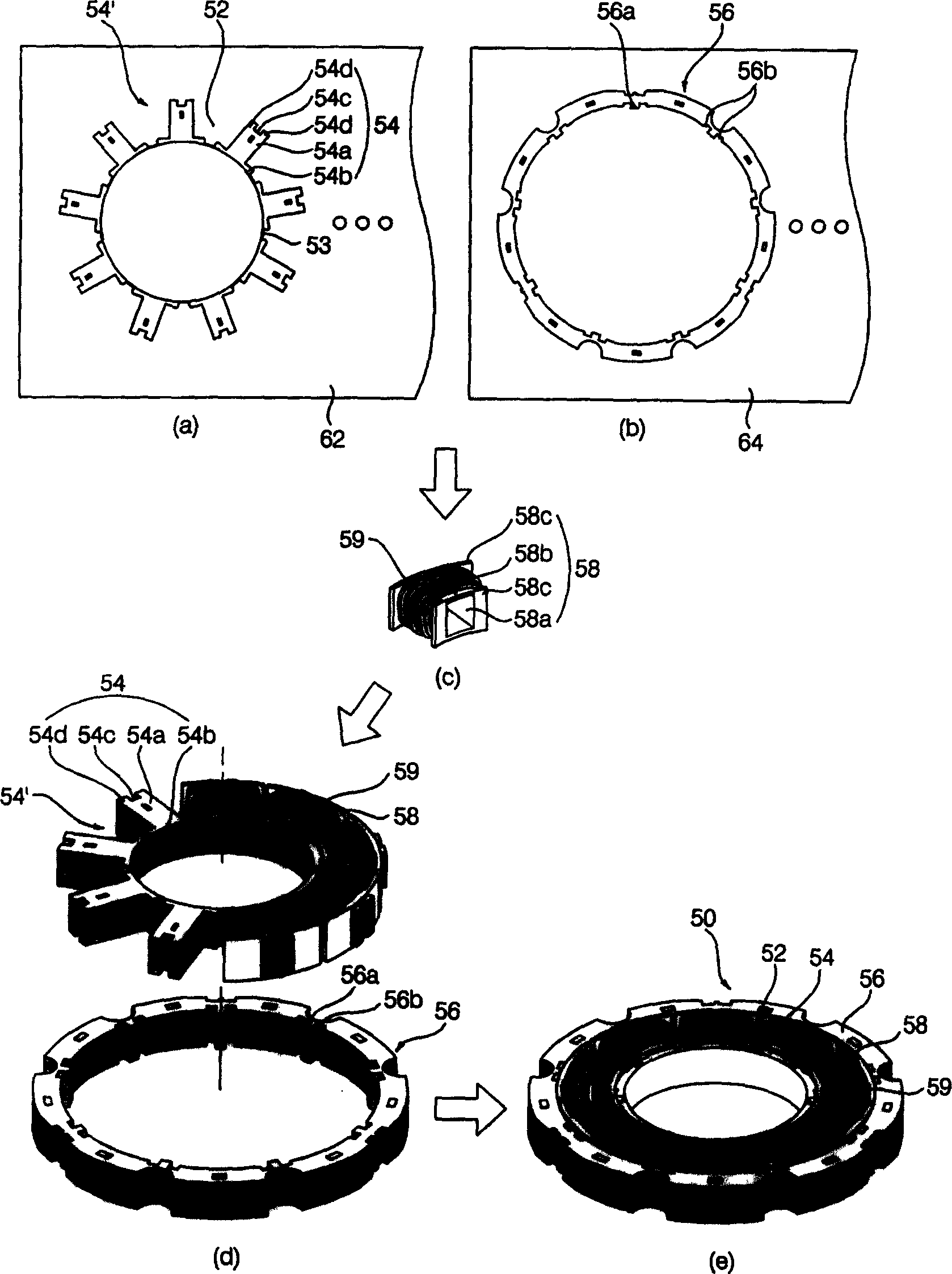
[0018] The motor stator 50 of the present invention is made through the following process, namely: tooth forming process ( figure 2 a), in this process, several teeth 54 need to be formed, and these teeth 54 are arranged along the circumferential direction of the rotor 60 while retaining certain slots 52; the yoke forming process ( figure 2 b), in this process, it is necessary to form a strip-shaped magnetic yoke 56 for connecting the above-mentioned several teeth 54; the winding process ( figure 2 c), in this process, coils 59 need to be wound on bobbins 58 that can be respectively inserted into the outsides of the above-mentioned teeth 54; the assembly process ( figure 2 d), in this process, it is necessary to insert the bobbins 58 wound with the above-mentioned coils 59 between the teeth 54 respectively, and then connect the above-mentioned teeth...


PUM


Abstract

In the disclosed method, magnetic yoke and teeth are formed dividually, and they can be inserted into connection structure one another. Winding is enwound on reel located on outside of each tooth. Then, reel with winding being enwound is inserted into tooth respectively. Finally, teeth are connected to magnetic yoke so as to produce stator completely. Advantages are: pin in use for enwinding winding is not intervened by circumference; windings can be enwound on reel as much as possible; efficiency of motor is raised and winding operation becomes handy.

Description

technical field [0001] The present invention relates to a manufacturing method of a stator of a motor (Manufacturing Method of Stator), more precisely, relates to a manufacturing method of a stator of a motor having the following characteristics: firstly forming a yoke and teeth respectively, and then winding the coils on the teeth The spools are inserted separately, and finally the yoke and teeth are assembled. Background technique [0002] The motor of prior art is made of following parts: stator 10, is fixed on the hood (housing) (not shown in the figure) of motor, and it is connected with external power supply; Rotor 20, is installed in the inside of above-mentioned stator 10 and can rotate , if an external power source is connected to the above-mentioned stator 10, an electromagnetic action is generated between it and the above-mentioned stator 10, thereby rotating. [0003] Specifically, the above-mentioned stator 10 is composed of the following components, namely: a ...

Claims


Application Information

Patent Timeline
Patent Type & Authority Applications(China)
IPC IPC(8): H02K15/02H02K15/08H02K15/095
Inventor 安埈澔赵官烈
Owner LG ELECTRONICS (TIANJIN) APPLIANCES CO LTD
Why Eureka
Try Eureka