
Structure for reinforcement pin in electrical connector

An electrical connector and connector technology, which is applied to the parts, connections, and fixed connections of connecting devices, and can solve problems such as interruptions and difficulties.

Inactive Publication Date: 2005-05-18
MORRIS CORP
View PDF0 Cites 0 Cited by
  • Summary
  • Abstract
  • Description
  • Claims
  • Application Information

AI Technical Summary

Problems solved by technology

[0006] In addition, due to the bending of the connecting pins, the electrical contact between the electrical contacts on the printed circuit board and the connecting pins is interrupted
In addition, for the above-mentioned reinforcing pins with the conventional structure, it is difficult to accurately form the corresponding insertion part on the connector housing, that is, since the size of the connector housing is very small, the connector housing It is very difficult to form a "U"-shaped plug-in portion corresponding to the shape of the reinforcing pin

Method used


Image

  • Structure for reinforcement pin in electrical connector
  • Structure for reinforcement pin in electrical connector
  • Structure for reinforcement pin in electrical connector

Examples


Embodiment Construction

[0025] Hereinafter, embodiments of the present invention will be described with reference to the accompanying drawings. In the following description and drawings, the same or similar components will be denoted by the same reference numerals, and repeated descriptions of the same or similar components will be omitted.

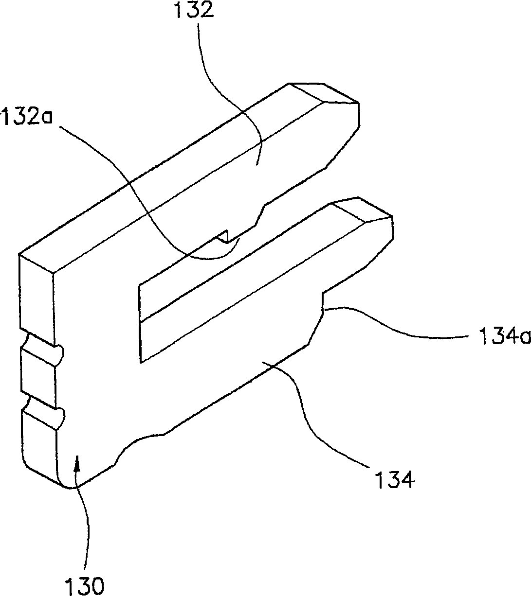
[0026] Figures 3 to 9 A female connector 100 according to the invention is shown. Such as Figures 5 to 9 As shown, the female connector 100 includes a connector housing 110, which has an insertion hole 112 and an insertion portion 114, a male connector (not shown) is inserted into and passes through the insertion hole 112, the insertion Portions 114 are formed on the sides on the front surface of the case for inserting reinforcing pins 130 . Connecting pins 120 are also provided, and each pin 120 has a first electrical contact portion 122 electrically connected to the electrical contact portion 210 on the printed circuit board 200 by welding, and a compleme...


PUM


Abstract

The invention discloses a structure of a reinforcing pin (130) in an electrical connector (100). The electrical connector comprises a connector housing (110), a connecting pin (120) installed in the housing and electrically connected to an electrical contact portion (210) on the printed circuit board (200), and Reinforcing pins (130) on each side of the lower front surface of the body (110). The insertion part (114) formed on the lower side of the connector housing for accommodating the reinforcement pin (130) includes upper and lower insertion slots (114a, 114b) formed together. Each reinforcing pin (130) has upper and lower insertion parts (132, 134), which correspond to the upper and lower insertion parts (114) in the connector housing (100), respectively inserted into the upper and lower insertion grooves and cooperation. A portion at the front of each lower insertion slot (114b) has a lower opening side. The reinforced pin (130) part protrudes from the lower side of the lower socket slot and is adapted to be soldered to a fixed contact portion on the printed circuit board. When the connector (100) including the reinforcing pin (130) is fixed on the printed circuit board (200) by soldering, the reinforcing pin (130) can prevent the connecting pin from being connected when the connector is bumped or vibrated. (120) Bending effect.

Description

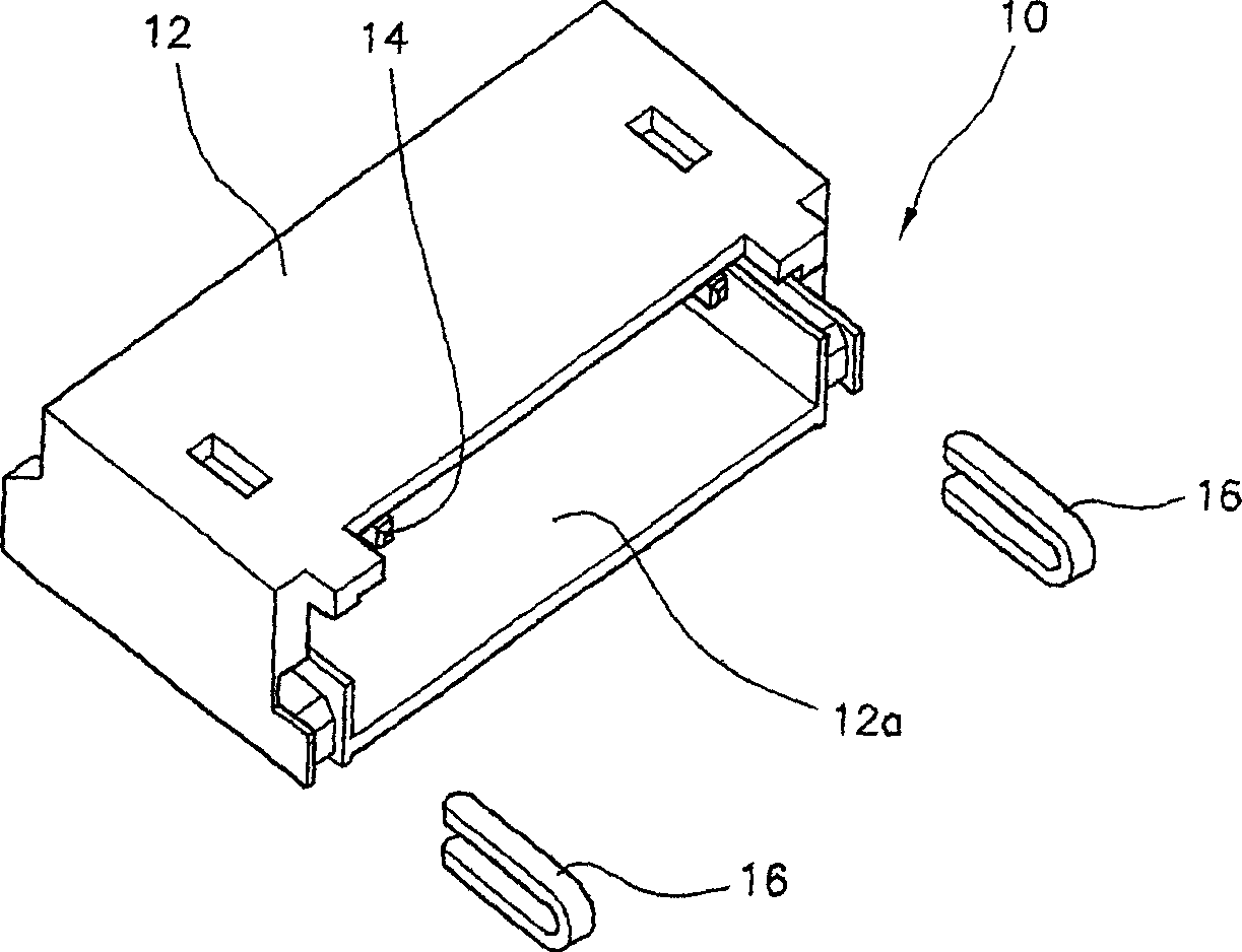
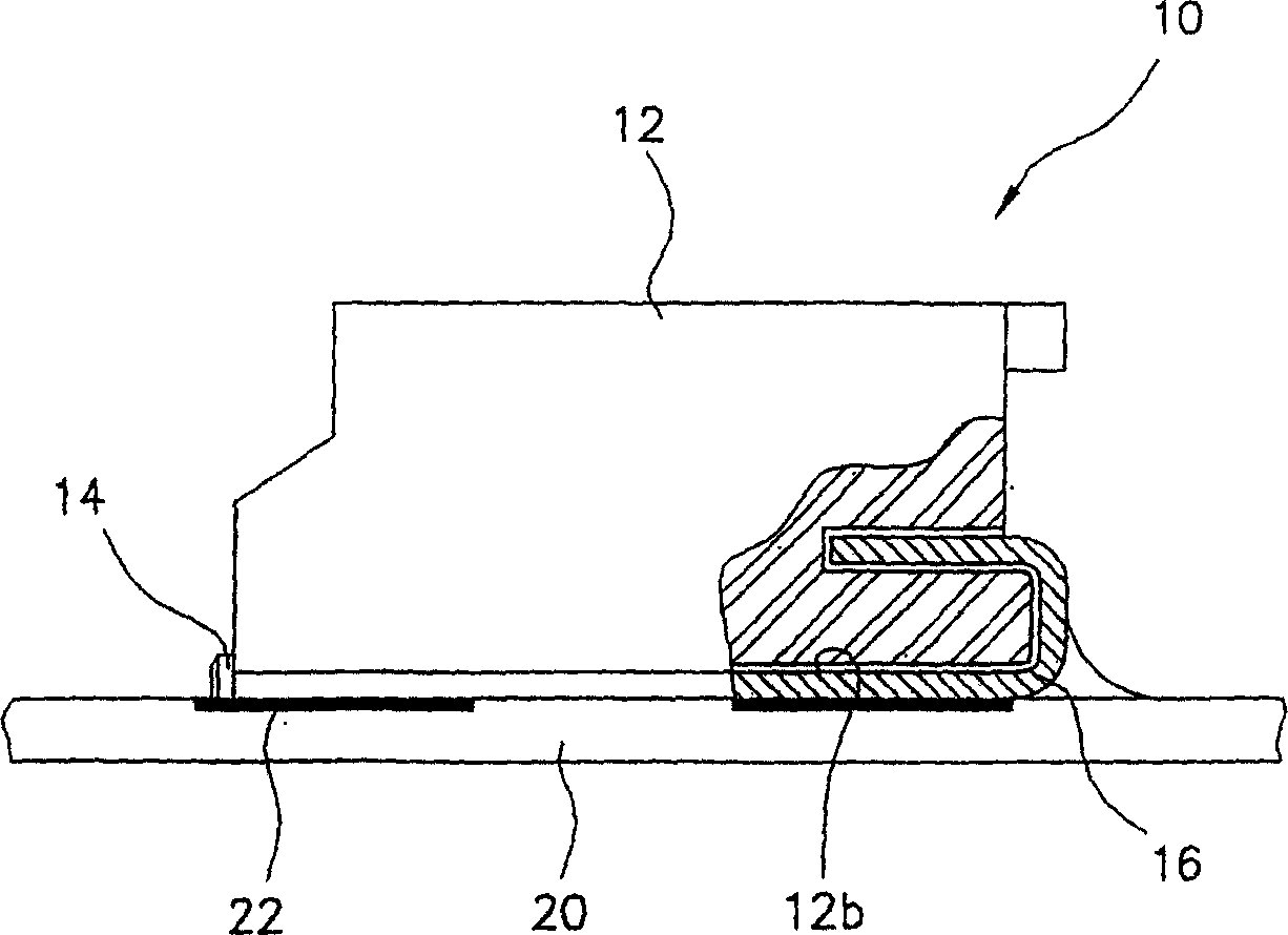
technical field [0001] The invention relates to a structure for reinforcing pins of an electric connector, and the design of the pins can prevent the electric contact portion of the connector from bending. Background technique [0002] In this field, electrical connectors are usually used to establish electrical connections between input and output terminals of electronic equipment such as notebook computers and camcorders. Where such connectors are mounted on a printed circuit board, one or more stiffener pins may be mounted on the connector housing and soldered to the board to help secure the connector to the board, reducing the The pressure on the mating face of the connector terminal and the solder connection face. An example of the structure of a traditional reinforcing pin will be introduced below with reference to FIGS. 1 and 2 . FIG. 1 is an exploded view of a female connector 10 mated with conventional reinforcing pins 16 . FIG. 2 is a partial cross-sectional vie...

Claims


Application Information

Patent Timeline
Patent Type & Authority Applications(China)
IPC IPC(8): H01R12/04H01R12/55H01R12/57H01R12/70H01R12/71H01R13/639
CPCH01R12/57H01R12/707H01R12/716H01R13/639
Inventor 金张范
Owner MORRIS CORP
Learn More