
Intravenous device

A technology of injectors and propulsion devices, which is applied in the field of intravenous injection devices, can solve the problems of increased penetration depth, etc., and achieve the effects of increasing accuracy, reducing unnecessary pain, and reducing overall costs

Active Publication Date: 2005-05-25
MICRO-STAR INTERNATIONAL
View PDF0 Cites 0 Cited by
  • Summary
  • Abstract
  • Description
  • Claims
  • Application Information

AI Technical Summary

Problems solved by technology

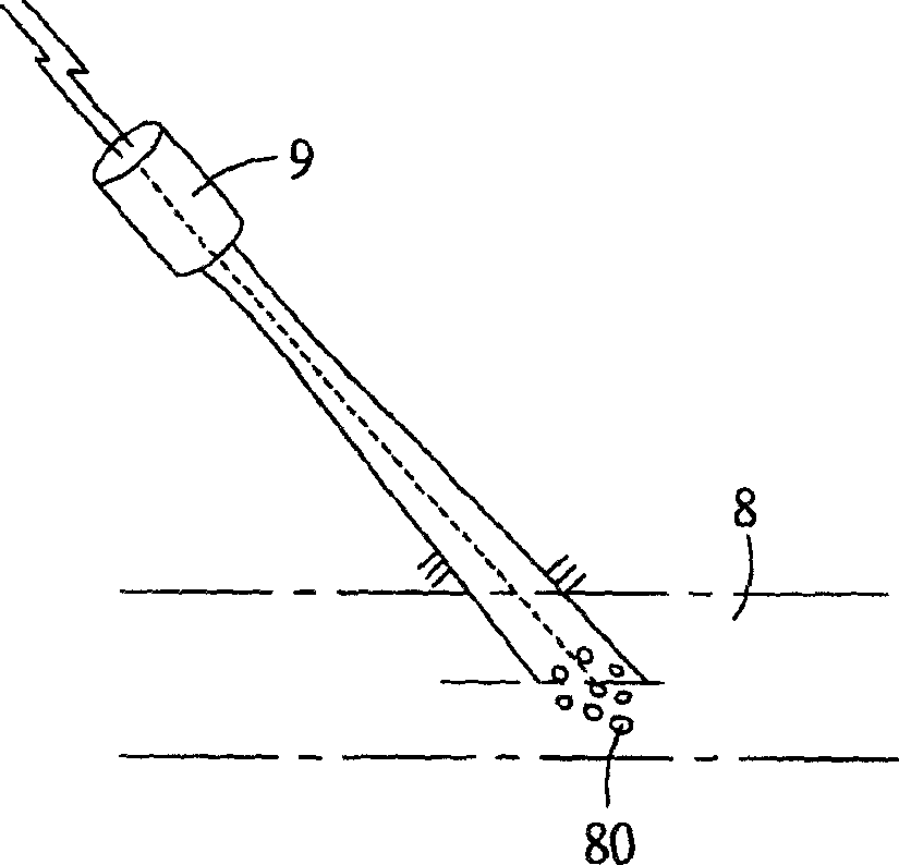
[0008] However, since there is a large angle between the injector 74 fixing device 73 of this application and the direction in which the ultrasonic probe 72 emits the ultrasonic signal, it means that medical personnel need to obtain a three-dimensional image between the blood vessel and the probe from the echo signal of the ultrasonic wave. information, and once the injector 74 is inserted into the body at an incorrect angle, the error will increase with the penetration depth, and it is impossible to make a turn afterward to remedy the situation, so it is necessary to pull out the injection again; on the other hand, because the distance between the injector 74 and the ultrasonic probe 72 is so far, The user must hold both of them with both hands, which is very inconvenient for both the injectee and the operator.

Method used


Image

  • Intravenous device
  • Intravenous device
  • Intravenous device

Examples


Embodiment Construction

[0049] The aforementioned and other technical contents, features and functions of the present invention will be clearly presented in the following detailed description with reference to the accompanying drawings and two sets of preferred embodiments.

[0050] refer to Image 6 and Figure 7 , the intravenous injection device 1 of the present invention includes a base 2 , a propulsion device 3 , and a syringe 4 .

[0051] The base 2 includes a longitudinal housing 20 , a pulsed ultrasonic probe 21 and a microprocessor 22 accommodated in the housing 20 . For the purpose of illustration, the front end 201 is defined as the end of the casing 20 facing the body part to be injected of the subject to be injected. In order to avoid interference from other factors, the ultrasonic probe 21 is assembled at the front end 201 of the casing; the ultrasonic probe 21 actually includes An oscillation device 211 and a detection device 212 . In this example, when the microprocessor 22 sends a...


PUM


Abstract

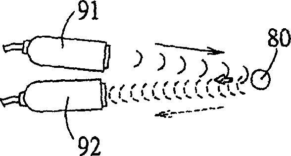
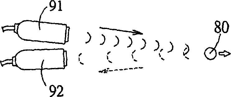
An intravenous injector has a pulse ultrasonic probe, which can emit the ultrasonic pulses and receive their echo to calculate the vein depth according to Doppler effect, and a push unit for automatically inserting the needle of injector into proper depth.

Description

technical field [0001] The invention relates to an intravenous injection device, in particular to an intravenous injection device positioned by an ultrasonic vein detection device. Background technique [0002] At present, for the medical behavior of using endoscope to penetrate into the human body to perform surgery or to treat tumors with radiation, in order to ensure accuracy without damaging surrounding tissues and cells, other methods such as X-ray scanning and magnetic resonance imaging (MRI) are usually supplemented. and other objective aids. Allows the operator to have objective images for reference and comparison, and even complete simultaneous monitoring during treatment. [0003] On the contrary, when general subjects or patients receive blood tests or drug injections, experienced medical staff only select appropriate vein needles to draw blood samples or perform injections, and there is no similar objective reference data for comparison. However, the veins and ...

Claims


Application Information

Patent Timeline
Patent Type & Authority Applications(China)
IPC IPC(8): A61M5/00
Inventor 吴宗佑罗孟宗张仪中
Owner MICRO-STAR INTERNATIONAL
Learn More