
Railroad rail stress testing method

A technology for stress testing and rails, which is applied in the direction of measuring force, measuring devices, instruments, etc., can solve the problems of heavy driving influence, failure to obtain stress change process, and difficulty in automatic detection, etc., and achieve the effect of preventing rail swelling or breaking

Inactive Publication Date: 2005-05-25
吴良善 +1
View PDF2 Cites 24 Cited by
  • Summary
  • Abstract
  • Description
  • Claims
  • Application Information

AI Technical Summary

Problems solved by technology

This is a manual measurement method, which is difficult to achieve automatic detection
[0004] Chinese invention patent 02104896.7 discloses a test method for seamless track rail temperature force and locked rail temperature. This patent is a test method for measuring the stress caused by temperature on the rail by applying a horizontal force on the rail. It needs to be interrupted during the test. Driving, remove the rail fasteners, the test has a great impact on driving, and the operation is inconvenient
[0005] The above measurement methods all have a common shortcoming, that is, complex preparations are required for each measurement, and the measurement equipment is moved to the railway. Read the stress data of the railway rail anytime and anywhere, let alone obtain the continuous stress change process; the measurement method of pasting the strain gauge on the outside of the rail is difficult to be used as a routine measurement method due to the harsh outdoor environment of the rail, which is easy to fail and peel off use

Method used


Image

  • Railroad rail stress testing method
  • Railroad rail stress testing method
  • Railroad rail stress testing method

Examples


Embodiment Construction

[0017] Specific embodiments of the present invention will be described in detail below in conjunction with the accompanying drawings.

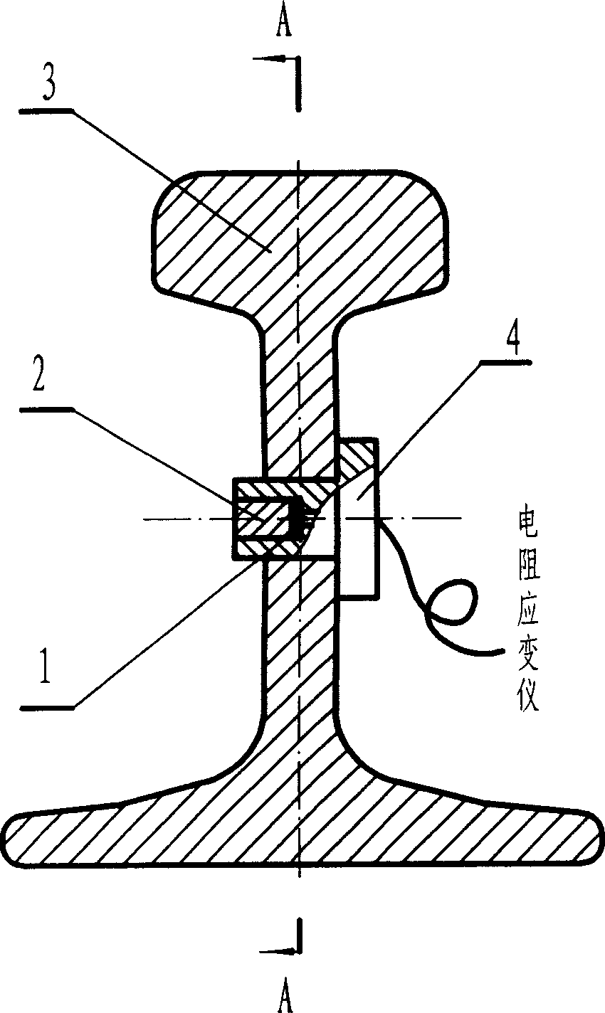
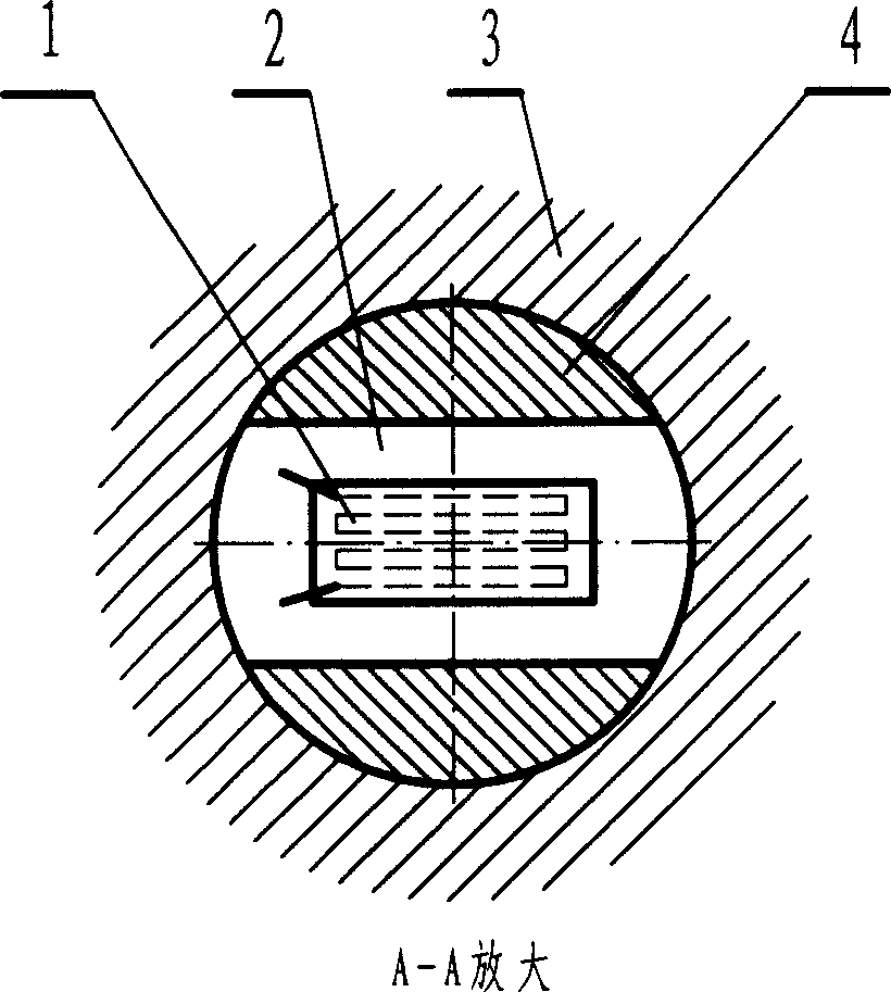
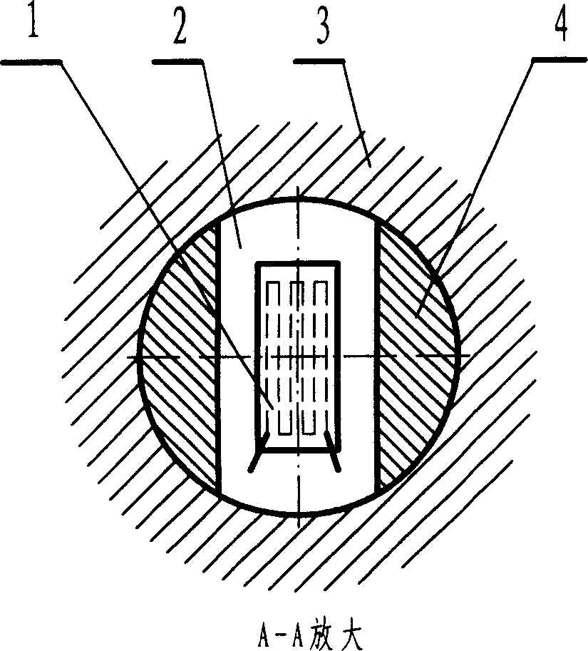
[0018] Such as figure 1 As shown, the rail waist part of the tested rail 3 is processed by drilling-expanding-twisting-a high-precision hole, and its diameter is suggested to be 20 millimeters by railway technical regulations. A special force sensor is assembled in the hole by pressing in. The sensor is composed of the sensor body 4 and the force block 2, and the strain gauge 1 is pasted on the force block 2, in order to avoid the error caused by the difference in temperature coefficient between the sensor and the rail. , the force block 2 and the sensor body 4 are made of the same material as the measured rail 3, and the test recording equipment connected to the sensor is a resistance strain gauge. Before the sensor is used, use a tensile testing machine to calibrate the relationship between the different stresses on the rail and the output ...


PUM


Abstract

The present invention disclosed a method for testing railroad track stress. Said invention adopts a built-in special-purpose force-measuring sensor in the track to be tested to measure track stress. Said special-purpose force-measuring sensor is formed from sensor self-body and stressed block on which a strain foil is stuck. Said invention also provides the mounting method of the above-mentioned components and their application.

Description

technical field [0001] The invention relates to a stress test method for railway rails, in particular to an online rail stress test method under the operating conditions of railway lines. Background technique [0002] The test of railway rail stress is of great significance to the production of railway transportation, because it is easy to know the external force on the rail by detecting the stress of the rail, which can be used to measure the temperature force of the long seamless rail, the locked rail temperature, etc., but So far, both at home and abroad have not been able to solve this testing problem well. Existing measurement methods such as: lateral force measurement method, rail displacement measurement method, ultrasonic measurement method, etc., measuring devices include TS-2 rail temperature stress tester, long rail stress gauge, etc. [0003] Chinese utility model patent 91205496.4 discloses a long rail stress gauge, which indirectly measures the temperature str...

Claims


Application Information

Patent Timeline
IPC IPC(8): G01L1/22
Inventor 吴良善周越
Owner 吴良善
Learn More