Eureka AIR delivers breakthrough ideas for toughest innovation challenges, trusted by R&D personnel around the world.

Device and method for monitoring state of filter element

A filter element and state technology, which is applied in the field of devices monitoring the state of the filter element, can solve the problems of unsafe, inaccurate, and unrealistic large-scale manufacturing.

Inactive Publication Date: 2005-05-25
PUROLATOR ADVANCED FILTRATION
View PDF0 Cites 26 Cited by
  • Summary
  • Abstract
  • Description
  • Claims
  • Application Information

AI Technical Summary

Problems solved by technology

These systems often require the design of a different pressure differential switch for each different filter assembly, making large-scale manufacturing commercially impractical
In addition, elastics and moving parts often behave differently at different temperatures, making the system inconsistent, imprecise and unsafe

Method used


Image

  • Device and method for monitoring state of filter element
  • Device and method for monitoring state of filter element
  • Device and method for monitoring state of filter element

Examples


Embodiment Construction

[0018] The embodiments disclosed below are not intended to exhaust or limit the invention in the precise form described below. Rather, these embodiments were chosen to be illustrated so that those of ordinary skill in the art can derive inspiration therefrom.

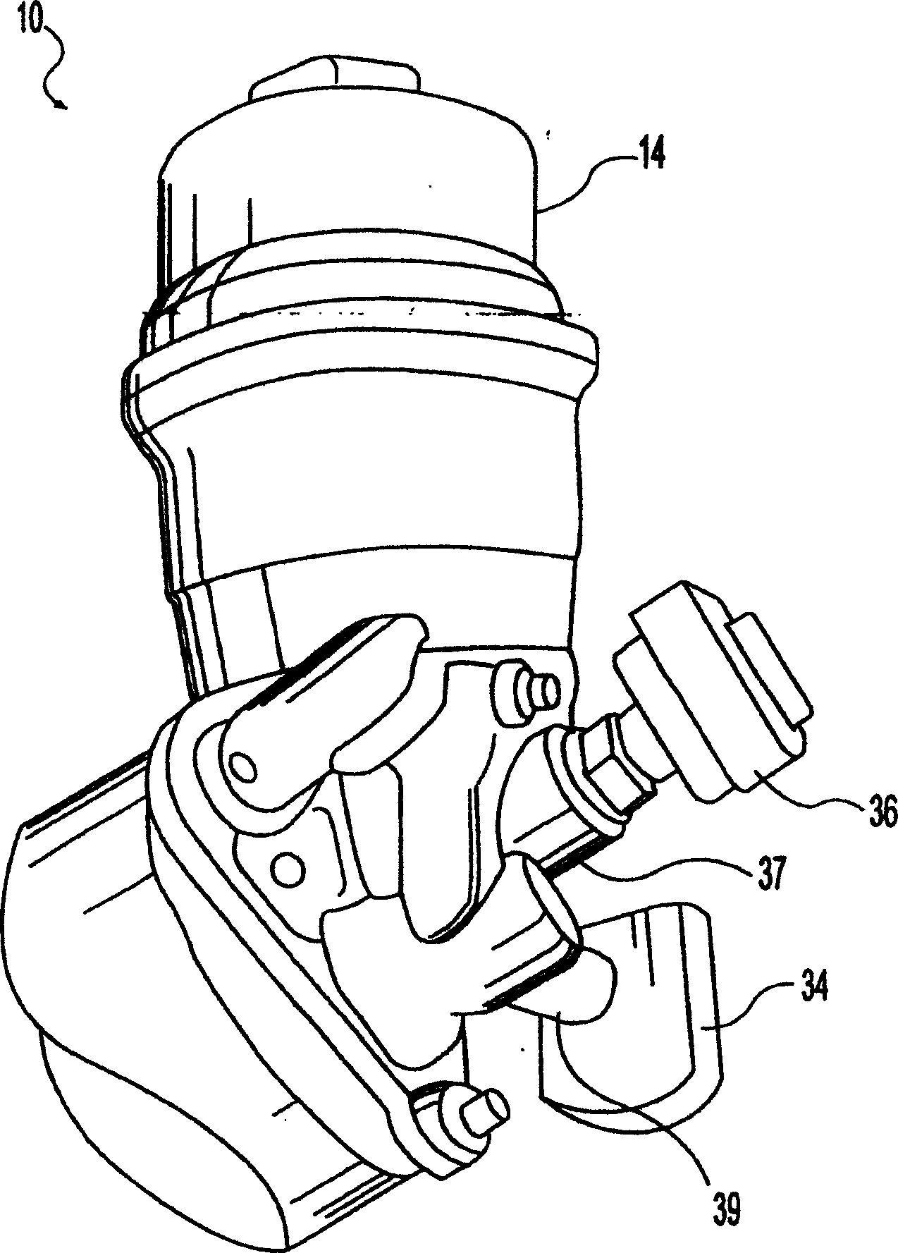
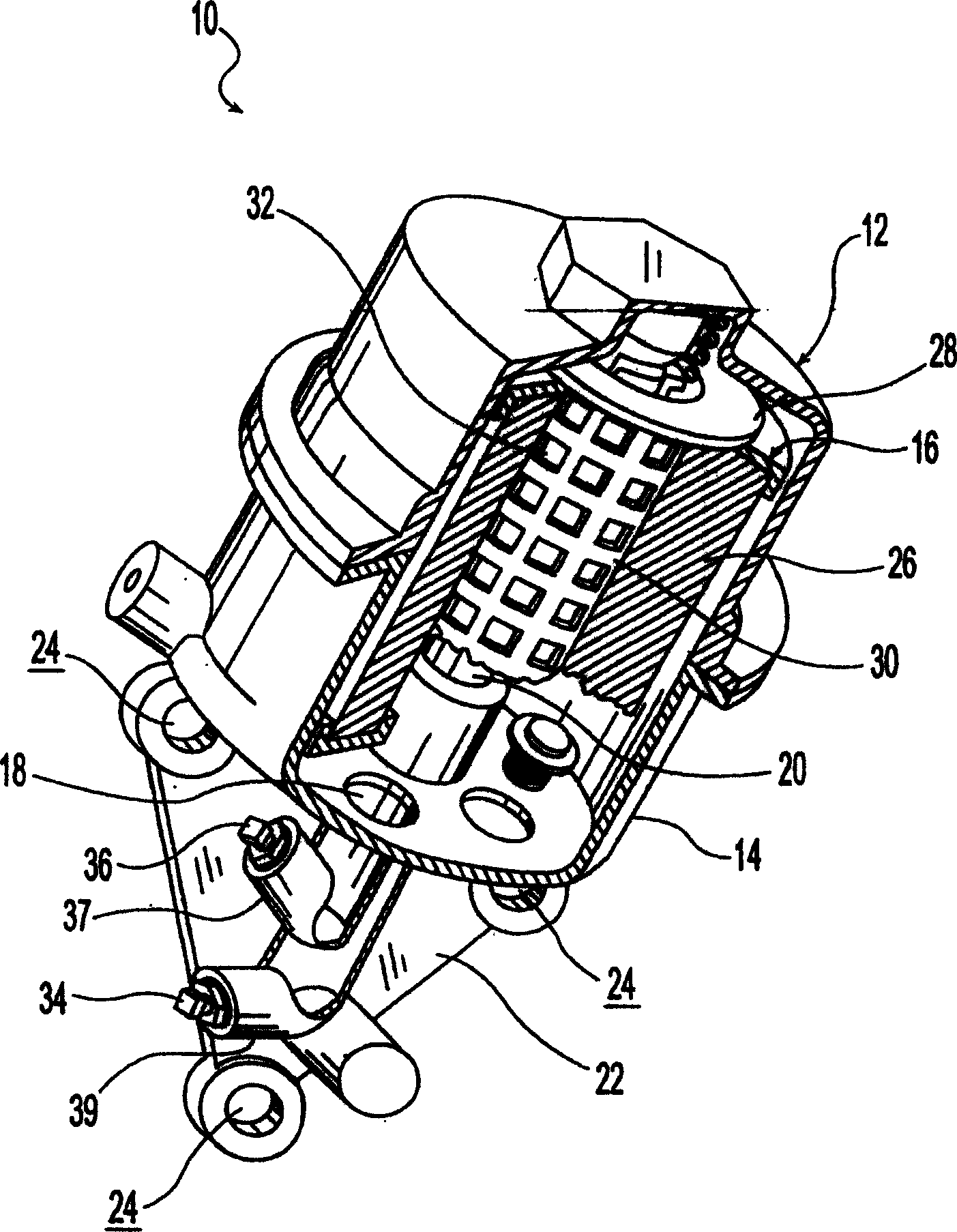
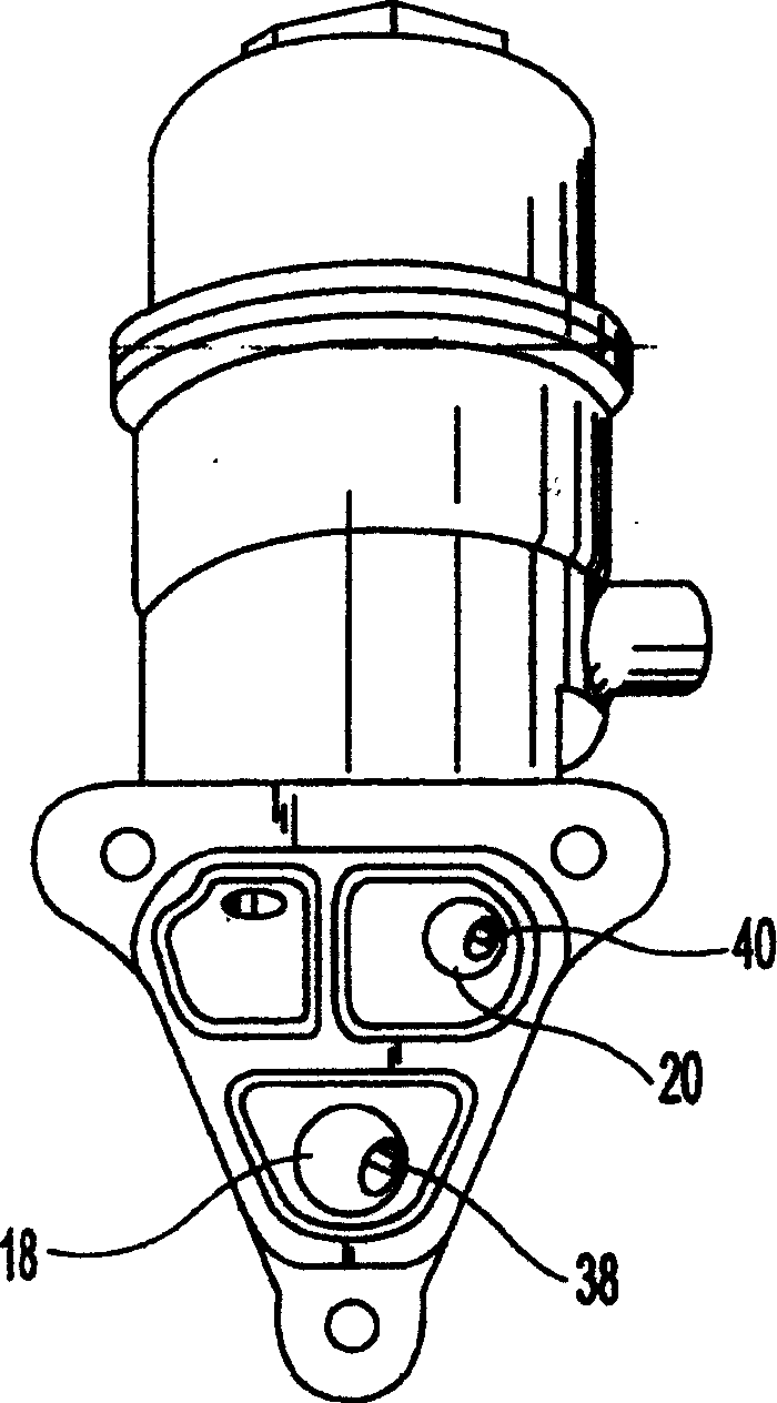
[0019] Figure 1-Figure 3 A fluid filter system 10 in one embodiment of the present invention is described. The filter system 10 includes a cartridge filter assembly 12 generally having a housing 14 , a cartridge cartridge 16 disposed in the housing 14 , at least one inlet passage 18 and one outlet passage 20 . The filter assembly 12 also includes a mounting flange 22 having mounting holes 24 through which mounting screws (not shown) can extend to attach the filter assembly 12 to an engine)))) on the group body. Inlet passage 18 and outlet passage 20 communicate fluid between the engine and the interior of housing 14 when mounted on the engine block body. The filter cartridge 16 includes a filter element 26 with a c...


PUM


Abstract

A filter system includes a filter assembly and a filter element condition monitoring assembly. The filter assembly has a housing, a filter element disposed within the housing, an inlet passage extending through the housing, and an outlet passage extending through the housing, the outlet passage being connected to the inlet The passages are communicated via the filter element; the filter element condition monitoring assembly has an inlet pressure sensor connected to the inlet passage, an outlet pressure sensor connected to the outlet passage, and an outlet pressure sensor connected to the inlet pressure sensor and the outlet pressure sensor A microprocessor, the inlet pressure sensor measures inlet pressure in the inlet passage, and the outlet pressure sensor measures outlet pressure in the outlet passage. The microprocessor calculates the differential pressure between the inlet pressure and the outlet pressure, and calculates the condition of the cartridge state using at least one filter cartridge state parameter, which parameter may include the differential pressure.

Description

technical field [0001] The present invention relates to filters, and more particularly to devices for monitoring the condition of filter elements. Background technique [0002] Internal combustion engines are often equipped with filter assemblies to filter out particulate impurities such as metals from engine wear, carbon from fuel combustion, and mineral dust in the air that can cause damage to the moving parts of the engine. Such cartridge assemblies may include oil filters, fuel filters, and air filters. The filter assembly generally includes a housing, a filter element disposed in the housing and two passages, namely an inlet passage and an outlet passage, and the two passages are communicated through the filter element. [0003] During the cycle, unfiltered (contaminated) fluid flows into the housing and then through the filter element, where particulate impurities are retained by the filter element. The resulting filtered (clean) fluid then exits the housing through ...

Claims


Application Information

Patent Timeline
Patent Type & Authority Applications(China)
IPC IPC(8): F01M1/18B01D35/02B01D35/143B01D46/42F01M11/10F02M37/22
CPCB01D35/143B01D46/0086B01D46/444B01D46/448B01D2201/54
Inventor 阿朗·K·巴华查丹尼·R·奥利斯罗伯特·E·谢姆拉德
Owner PUROLATOR ADVANCED FILTRATION
Why Eureka
Eureka Blog
Learn More