Flexible diaphragm with integrated coil

A vibrating membrane and coil technology, applied in the direction of flat vibrating membrane, telephones with user guidance/use, non-planar vibrating membrane/paper cone, etc. question

Inactive Publication Date: 2005-05-25
桑尼昂霍森斯公司
View PDF1 Cites 3 Cited by
  • Summary
  • Abstract
  • Description
  • Claims
  • Application Information

AI Technical Summary

Problems solved by technology

[0008] A disadvantage of the diaphragm design in EP1 182 907 is that due to the thin and elastic diaphragm material a sufficiently rigid diaphragm has to be provided for the shape of the vibration curve
However, the curvature of the diaphragm in the direction of motion of the diaphragm requires sufficient height to extend, therefore, the result of the design is not flat in nature
Therefore, the diaphragm design in EP1 182 907 cannot be used in tiny loudspeakers where a flat design is crucial

Method used


Image

  • Flexible diaphragm with integrated coil
  • Flexible diaphragm with integrated coil
  • Flexible diaphragm with integrated coil

Examples


Embodiment Construction

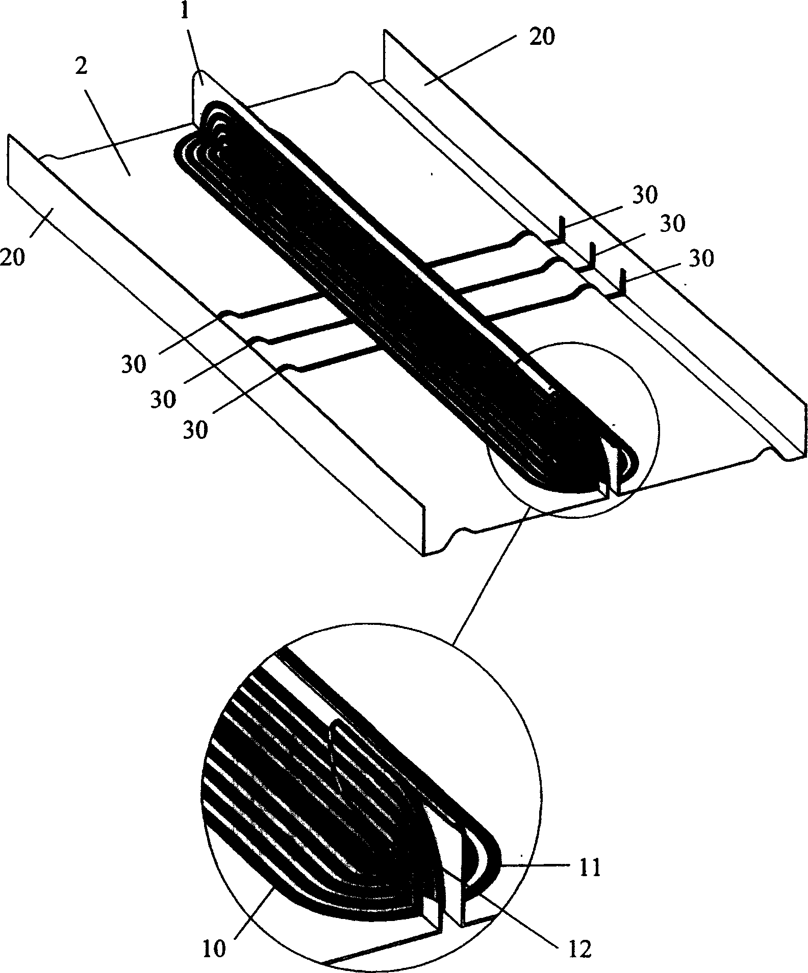
[0032] According to the invention, the coil may be formed from a thin and flexible sheet, such as a flexible printed circuit board, ie a flexible circuit board. Such a thin and flexible sheet will carry the predetermined conductive path thereon, forming a coiled conductive path. As described below, the diaphragm also has conductive portions in its preferred embodiment. Thus, the coil and diaphragm can be made from a single piece of flexible circuit board with corresponding conductive paths, the shape of this single piece can be made: the two long parts of the coil are exposed, and with respect to the rest of the integrated diaphragm / coil at a 90-degree angle.

[0033] figure 1 A preferred embodiment of the invention formed from a rectangular double-sided flexible circuit board is shown. figure 1 The diaphragm is shown viewed from the underside of the diaphragm, the side facing the magnetic path when mounted on a sensor. figure 1 The embodiment shown has a spacer portion 1 ...


PUM


Abstract

A diaphragm for an electroacoustic sensor, the diaphragm comprising: a flexible sheet comprising first and second thin segments, each of the first and second thin segments having a substantial plane; and one or more Each of the one or more coils has a conductive path in the plane of the first and second thin segments, thereby forming first and second coil segments for each coil, respectively. The flexible diaphragm can be realized by using a single-sided or double-sided flexible circuit board. An integrated diaphragm and coil system can be formed from a single piece of flexible circuit board. Diaphragms can be used in microphones or loudspeakers.

Description

technical field [0001] The invention relates to the field of electroacoustic sensors. In particular, the invention relates to integrated diaphragm and coil systems for use in electroacoustic sensors. Background technique [0002] Existing diaphragm and coil systems for use in electroacoustic transducers typically include a conductive coil formed by winding a metal wire wound on a bobbin. The spool is attached to a diaphragm, which converts the movement and displacement of the spool into an acoustic signal. The coil and part of the bobbin are located in a magnetic gap, thereby forming an electromagnetic drive means for driving the diaphragm in response to an electrical signal applied to the coil. [0003] In some miniature sensors, the bobbin is avoided by attaching the coil directly to the diaphragm, so only part of the coil is located in the magnetic gap. Although this method omits a large number of coils, the disadvantage is that part of the coils located in the magneti...

Claims


Application Information

Patent Timeline
Patent Type & Authority Applications(China)
IPC IPC(8): H04R9/00H04M1/03H04M1/247H04R7/12H04R9/04
CPCH04R9/047H04M1/03H04R7/12
Inventor 莱夫·约翰森莫藤·谢尔森·安诺生
Owner 桑尼昂霍森斯公司
Why Eureka
Try Eureka