Embossed reflective laminates

A technology of embossing and laminating glass, applied in the directions of lamination, lamination auxiliary operation, coating, etc., can solve the problem of not being able to reduce the surface defects of the infrared reflective surface

Inactive Publication Date: 2005-06-08
SOLUTIA INC
View PDF21 Cites 17 Cited by
  • Summary
  • Abstract
  • Description
  • Claims
  • Application Information

AI Technical Summary

Problems solved by technology

[0010] In fact, prior art methods are not able to reduce all surface defects on infrared reflective surfaces

Method used


Image

  • Embossed reflective laminates
  • Embossed reflective laminates
  • Embossed reflective laminates

Examples


Embodiment 1

[0047] Adhesive Treatment of PET Film Surface

[0048] Since PET film did not have sufficient adhesion to PVB, one surface of each of the two rolls of PET was subjected to a high vacuum "glow discharge" plasma treatment using an argon / nitrogen gas mixture to achieve an acceptable level of adhesion. The energy input and line speed in the process were chosen to maximize the adhesion of PVB to PET without appreciable yellowing of the PET film.

[0049] The 90° peel adhesion test is used to measure the bond strength between plasticized PVB and PET film. Special peel-adhesive laminates containing PET film are produced using standard lamination methods by replacing one glass sheet of a standard double-layer glass laminate with PET film.

[0050] The thickness of the plasticized PVB layer used was 0.030” (0.76mm), and it was dried at 70°C for 1 hour before use to reduce the moisture content to ensure that the adhesion of the glass / PVB interface was higher than that of the PET / PVB ...

Embodiment 2

[0054] PET film coating with aluminum

[0055] A roll of film (Example 1) that had been plasma-treated on one surface was placed in a vacuum chamber for "metallization". The pressure in the vacuum chamber was reduced by a series of vacuum pumps until it reached the evaporation pressure of aluminum (6.7 × 10 -2 Pa / 0.5 micron Hg). At this point, aluminum evaporates by resistively heating the aluminum source and deposits on the untreated PET surface. The deposition rate was controlled to obtain a coating about 50 Angstroms thick.

Embodiment 3

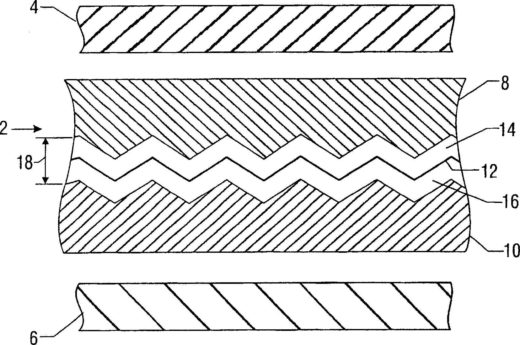
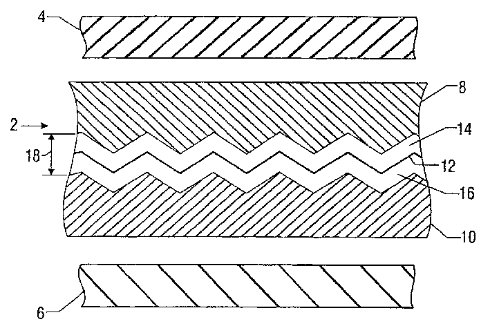
[0057] Lamination of metallized films (→ decorative composites)

[0058] To minimize oxidation of the aluminum surface, this roll of aluminum metallized film (Example 2) was laminated to the untreated surface of a second roll of PET film, which had previously been treated with an adhesion promoting treatment (Example 1). The decoration was obtained by bonding the aluminum coated surface of one film to the untreated surface of the other film using an isocyanate-crosslinked polyester binder system using conventional two-layer coating / dry / roll lamination methods. composite material.

[0059] The visible light transmission of the laminated film was measured with a Perkin-Elmer Lambda 900 spectrophotometer with a 150 mm diameter collecting sphere and found to be 31.4%. A D65 Illuminant at a 10° observation well was then used for the measurements.


PUM

PropertyMeasurementUnit
thicknessaaaaaaaaaa
thicknessaaaaaaaaaa
transmittivityaaaaaaaaaa

Abstract

This invention provides an embossed decorative composite laminate interlayer for use in reducing UV and IR energy transmittance through a glass laminate. One interlayer of the present invention comprises an embossed decorative composite disposed between a first and second adhesive layer, such as PVB. The embossed decorative composite of the present invention comprises a first polymeric support film, such as PET, having a metal coating disposed thereon, thereby forming a metallized film. The metallized film is then bonded through the use of an adhesive to a second polymer support film, forming a decorative composite structure. The decorative composite is then purposefully embossed such that they have protrusions at different angles to the flat plane of the bonded polymeric support films, so as to form the desired embossed decorative composite.

Description

Background technique [0001] The present invention relates to the application of a shatter resistant laminate window arrangement with a high solar radiation reflectivity and a uniform appearance, which has not been previously used in architectural and automotive applications. [0002] Due to the popularity of new sports vehicles (SUVs) in the United States and elsewhere, the surface area of ​​automotive glass has increased in recent years, creating a need to reduce the solar heat load of the vehicle. Also, there is a lot of interest in increasing the privacy of vehicles to improve the safety of people. As the rear and rear glazing and sunroofs of these vehicles are often governed by less restrictive government regulatory Visible light transmission and limited aesthetics. [0003] In architectural applications, metal-coated glass with high visible reflectance is undesirable due to detrimental "mirror-like" reflections. Moreover, in certain urban areas with high building densi...

Claims


Application Information

Patent Timeline
Patent Type & Authority Applications(China)
IPC IPC(8): B32B15/08B32B3/30B32B17/10B32B27/36C03C27/12
CPCB32B3/30B32B17/10036B32B17/10174B32B17/10247B32B17/10577B32B17/10761B32B17/10816B32B27/36Y10T428/24479Y10T428/24612Y10T428/24628Y10T428/24521Y10T428/24545Y10T428/2848Y10T428/24529Y10T428/28Y10T428/3163Y10T428/31678B32B17/10005B32B2367/00B32B15/08B32B38/0008
Inventor 詹姆斯·R·莫兰
Owner SOLUTIA INC
Why Eureka
Try Eureka