Braking arrangement

A braking and cylinder technology, applied in safety devices, hydraulic brakes, engine components, etc., can solve problems such as machine damage, brake overtravel ejection, etc., and achieve the effects of simple structure, reliable operation, and uniform force

Inactive Publication Date: 2005-06-29
郭炜
View PDF0 Cites 2 Cited by
  • Summary
  • Abstract
  • Description
  • Claims
  • Application Information

AI Technical Summary

Problems solved by technology

There is no limit to the stroke of the brake piston. When the brake is used as a jack to lift the rotor, someone must observe its stroke on the spot to start and stop the oil pump, otherwise the brake will be pushed out beyond the stroke, causing machine damage

Method used


Image

  • Braking arrangement

Examples


Embodiment Construction

[0010] The specific implementation, structure, features and effects provided by the present invention will be described in detail below in conjunction with the accompanying drawings and preferred embodiments.

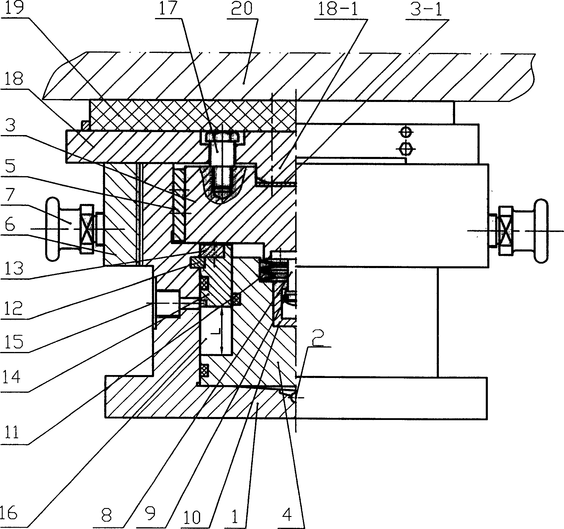
[0011] Such as figure 1 Shown, a kind of braking device that is used for hydroelectric generating set, it has cylinder body 1, is provided with oil inlet air inlet hole 2 on the cylinder body, upper piston 3, lower piston 4 are housed in the cylinder body, upper piston and A limit key 5 is installed between the inner wall of the cylinder, and a lock nut 6 and a handle 7 for adjusting and locking the upper piston are installed outside the cylinder body, and the top of the cylinder body 1 and the upper piston 3 is eccentrically fixed and connected with the brake supporting plate 18 and the brake by the positioning bolt 16. Brake shoe 19, the bottom end of its brake supporting plate 18 is shaped on a spherical convex head 18-1, which is installed in the groove 3-1 on the t...


PUM


Abstract

The invention relates to a braking device. There are oil inlet and air holes on the cylinder body, the upper piston and the lower piston are installed in the cylinder body, the limit key is installed between the upper piston and the inner wall of the cylinder body, the nut and handle for adjusting and locking the upper piston are installed outside the cylinder body, the cylinder body and the upper piston The top of the piston fixes the brake pallet and brake shoe eccentrically through the positioning bolt. The lower part of the upper piston is fixedly connected with the piston core. The lower end of the piston core is clamped in the core sleeve of the inner cavity of the lower piston. , the limit sleeve installed between the lower piston and the cylinder body is connected with the inner wall of the cylinder through the ring key and the pressure ring, and the lower piston at the bottom of the limit sleeve and the inner cavity of the cylinder form a gas return working chamber as a mechanically limited space, corresponding to the gas return work The cylinder body of the chamber is provided with a gas return hole communicating with it. The invention has the advantages that: the stroke of the piston is limited by the mechanical limiting device, the piston always moves up and down in a straight line, and the piston is reset by air pressure, which is reliable, safe and flexible.

Description

technical field [0001] The invention relates to a braking device, in particular to a braking device for a hydraulic generator set. Background technique [0002] The traditional braking device of the hydro-generator set adopts a return compression spring placed in the center of the upper end of the single piston. Since the brake ring will generate a lot of heat and deformation when the hydro-generator set stops and brakes, the brake valve tile and the brake Ring friction will generate a large friction force, causing the brake valve shoe to bear an overturning moment during braking, causing the piston to deflect and get stuck with the cylinder wall, so that it cannot work again. In order to solve the above-mentioned disadvantages, a brake based on the eccentric principle has appeared in recent years, using structures such as eccentric, guide, and disc springs. Although the practical performance of the brake has been improved, the problem of overturning moment has not been comp...

Claims


Application Information

Patent Timeline
Patent Type & Authority Applications(China)
IPC IPC(8): F03B13/10F03B15/00F16D55/10
CPCY02E10/20
Inventor 郭炜
Owner 郭炜
Why Eureka
Try Eureka