
Liquid crystal display capable of adjusting visual angle and method of adjusting visual angle thereof

A liquid crystal display and viewing angle technology, which is applied to static indicators, instruments, nonlinear optics, etc., can solve the problems of decreased display brightness, inability to switch viewing angles, and inconvenient use

Inactive Publication Date: 2005-06-29
AU OPTRONICS CORP
View PDF0 Cites 9 Cited by
  • Summary
  • Abstract
  • Description
  • Claims
  • Application Information

AI Technical Summary

Problems solved by technology

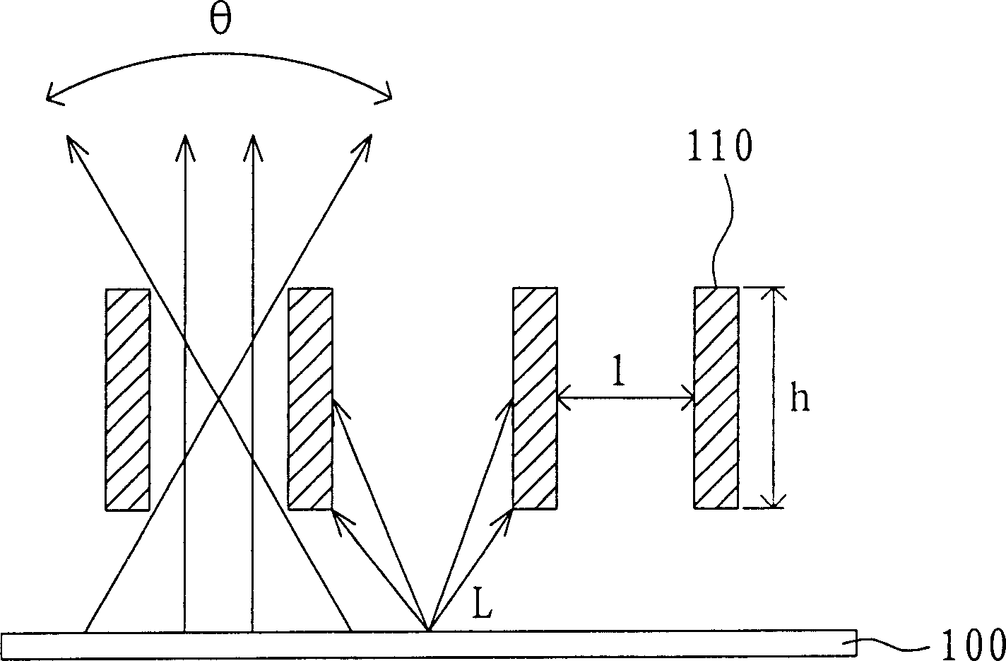
[0004] However, the disadvantage of this viewing angle control method is that: the louvered absorbing structure 110 must be added outside the display when in use, causing inconvenience in use; as part of the light L is absorbed by the louvered absorbing structure 110, the display brightness will decrease. It has dropped by more than half; and the adjustment of its viewing angle is to increase or decrease at the same time, which cannot meet the various needs of users for viewing angle switching, such as providing users with only front view and left side view.
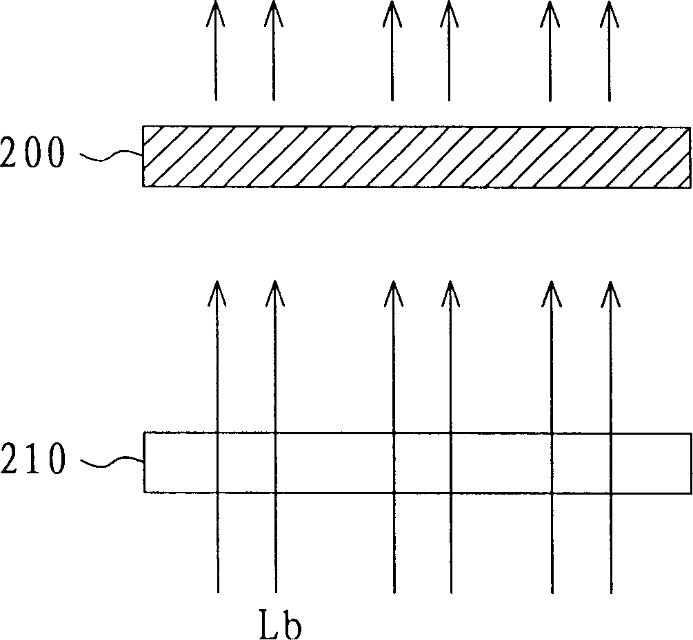
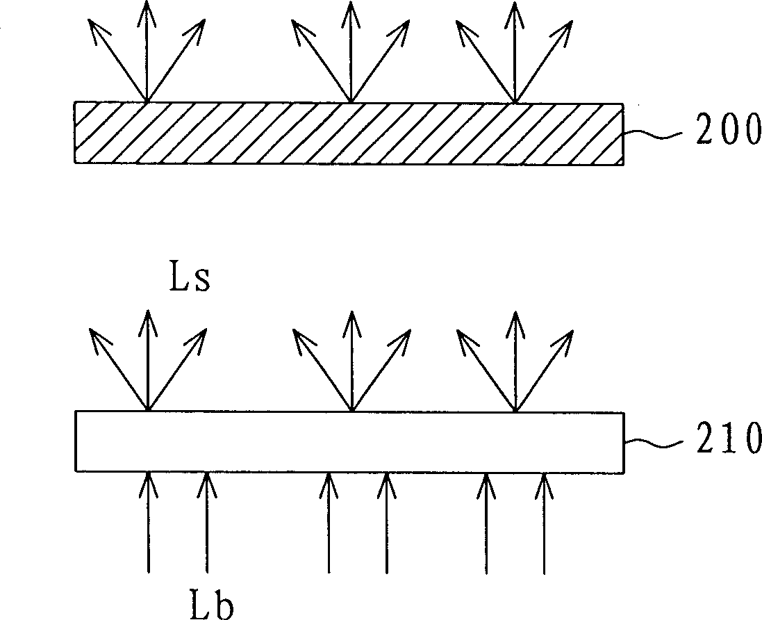
[0006] However, the disadvantage of this viewing angle control method is that: when the light scattering structure 210 is switched to the voltage-on state, the backlight Lb will be partially reflected when passing through the light scattering structure 210, causing the brightness of the liquid crystal panel 200 to decrease; and as above As mentioned in an example, this viewing angle control method can only provide two modes of narrow viewing angle and wide viewing angle, and cannot be adjusted according to the viewing angle required by the user, thus limiting the variety of options for viewing angle adjustment
[0008] However, as described in the above three examples, the current LCD structures with adjustable viewing angles often have the disadvantages of decreased brightness and reduced contrast when switching viewing angles, and cannot switch the viewing angle to a viewing angle other than the one required by the user. , so neither is a true viewing angle adjustment method

Method used


Image

  • Liquid crystal display capable of adjusting visual angle and method of adjusting visual angle thereof
  • Liquid crystal display capable of adjusting visual angle and method of adjusting visual angle thereof
  • Liquid crystal display capable of adjusting visual angle and method of adjusting visual angle thereof

Examples


example 1

[0029] Please refer to Figure 5A and Figure 5B , which is a simplified cross-sectional view of a liquid crystal display in a wide viewing angle operation mode according to the first example of the present invention. When the liquid crystal display 400 is in the wide viewing angle operation mode, the entire first liquid crystal layer 434 can be driven to a state where the phase delay Δnd1 is zero. For example, when the first pixel voltage is 0V, the liquid crystal molecules in the first liquid crystal layer 434 are in a straight state. At this time, the backlight Lb is incident to the second liquid crystal layer 444 through the first liquid crystal layer 434 , and the information to be displayed is determined by the second liquid crystal layer 444 . Of course, the entire second liquid crystal layer 444 can also be driven to a state where the phase delay Δnd2 is zero, and the information to be displayed is determined by the first liquid crystal layer 434 .

[0030] As shown i...

example 2

[0037] In the second example, the driving method of the wide viewing angle operation mode is the same as that of the first example. However, the way of driving the liquid crystal layers 434 and 444 in the narrow viewing angle operation mode is different from the first example.

[0038] Please refer to Figure 6A and Figure 6B , which is a simplified cross-sectional schematic diagram of a liquid crystal display in a narrow viewing angle operation mode according to the second example of the present invention. When the liquid crystal display 400 is in the narrow viewing angle operation mode, the information to be displayed can be partially represented by the liquid crystal layer 434 and partially represented by the liquid crystal layer 444 . When viewed squarely, as Figure 6A As shown, the phase delays Δnd1 and Δnd2 corresponding to the consecutive pixels P11 , P12 , and P13 in the liquid crystal layers 434 and 444 are both λ / 4 and 0, respectively. Therefore, the phase dela...

example 3

[0041] In the third example, the driving method of the wide viewing angle operation mode is the same as that of the first example. However, the way of driving the liquid crystal layers 434 and 444 in the narrow viewing angle operation mode is different from the first example.

[0042] Please refer to Figure 7A and Figure 7B , which is a simplified cross-sectional view of a liquid crystal display in a narrow viewing angle operation mode according to a third example of the present invention. When the liquid crystal display 400 is in the narrow viewing angle operation mode, the narrow viewing angle is not perpendicular to the direction of the liquid crystal layers 434 and 444 , but has a right oblique angle Ψ, such as 45 degrees. According to the angle Ψ, the backlight Lb that is transmitted through the liquid crystal layer 444 corresponding to the consecutive pixels A5 - A9 is emitted from the liquid crystal layer 434 corresponding to the pixels A1 - A5 . The phase delay Δn...


PUM


Abstract

It is a display device with adjustable vision angle, which comprises aphototropism elements, first display panel, second display panel and data driver. The first display panel is set above the aphototropism elements and comprises the first LCD layer and the first picture element electrode relative to each picture element. The second display panel is set above the aphototropism elements and comprises the second LCD layer and the second picture element electrode relative to each picture element. The data driver is coupled with the first and second display panels to drive the first and second picture element electrodes.

Description

technical field [0001] The present invention relates to a liquid crystal display with an adjustable viewing angle and a method for adjusting the viewing angle, and particularly relates to a liquid crystal display with an adjustable viewing angle by driving two liquid crystal layers and a method for adjusting the viewing angle. Background technique [0002] With the advancement of technology, consumers have more opportunities to use mobile products with displays in public areas, such as mobile phones, notebook computers, etc., but if consumers want to keep their privacy when using them in public areas, then they A monitor with adjustable viewing angle will be required. At present, there are the following three common methods for controlling the viewing angle of a liquid crystal display. [0003] figure 1 It is a schematic diagram of adjusting the viewing angle of a liquid crystal display by using blinds to absorb materials in the prior art. Please refer to figure 1 , add ...

Claims


Application Information

Patent Timeline
IPC IPC(8): G02F1/133G02F1/1335G02F1/136G09G3/36
Inventor 蔡孟璋张志明
Owner AU OPTRONICS CORP
Learn More