
Pixel drive circuit and method for active electroluminescent display

A pixel driving circuit, electro-luminescence technology, applied in electro-luminescence light sources, static indicators, instruments, etc., can solve the problem that the writing effect is not easy to accurately control and so on

Active Publication Date: 2005-06-29
AU OPTRONICS CORP
View PDF0 Cites 5 Cited by
  • Summary
  • Abstract
  • Description
  • Claims
  • Application Information

AI Technical Summary

Problems solved by technology

However, current-driven integrated circuits have bottlenecks in manufacturing technology and cost. In addition, when low current is written, the writing effect is difficult to accurately control due to internal impedance and capacitance effects.

Method used


Image

  • Pixel drive circuit and method for active electroluminescent display
  • Pixel drive circuit and method for active electroluminescent display
  • Pixel drive circuit and method for active electroluminescent display

Examples


Embodiment Construction

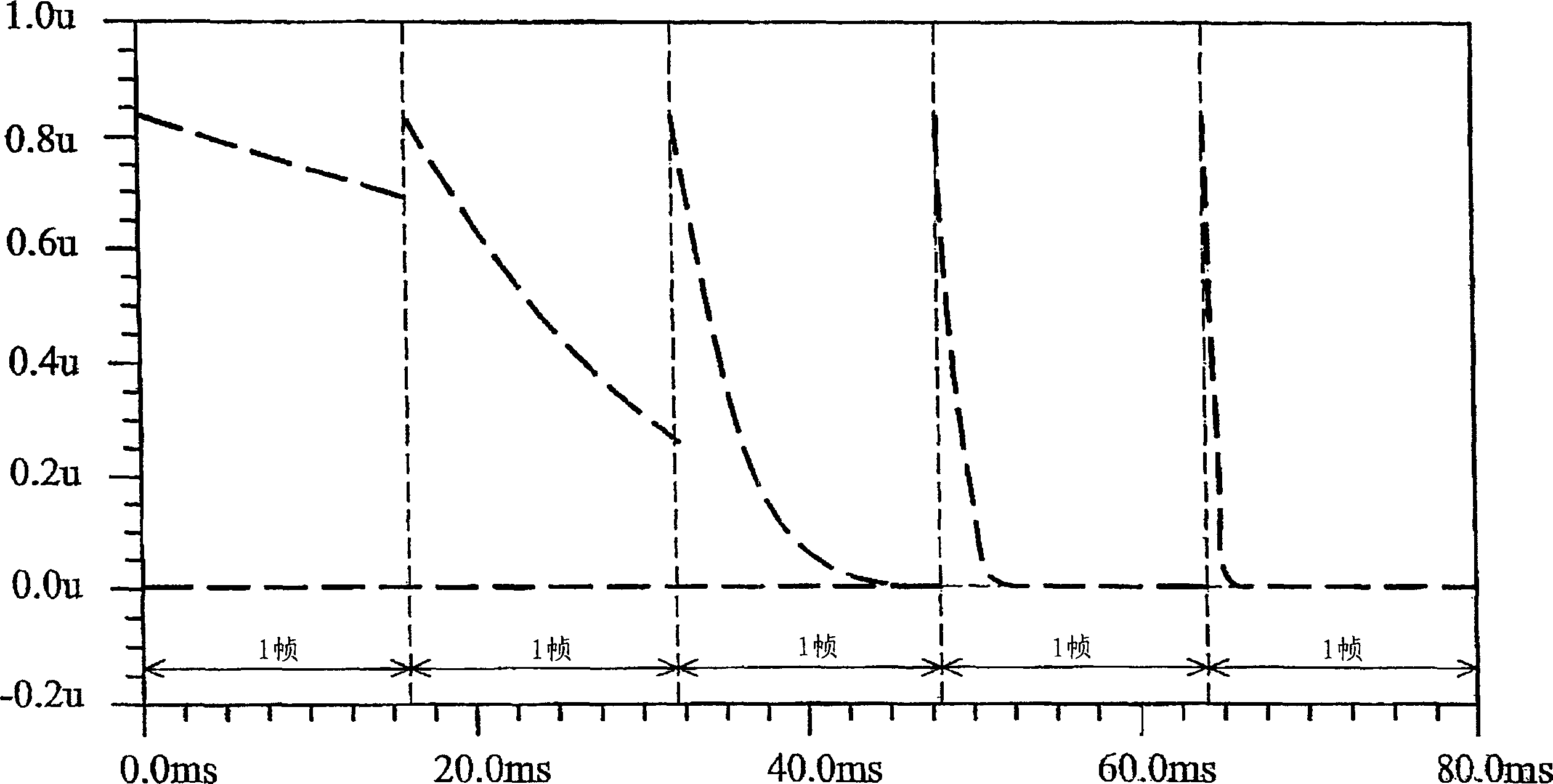
[0016] The concept of the present invention is to use a fixed current to charge a gray-scale voltage to a saturation value to drive a light-emitting diode to emit light, and then write a data signal in voltage mode to control the discharge speed of the gray-scale voltage, so that the The display time and brightness of the light-emitting diodes are changed to achieve the effect of controlling the gray scale.

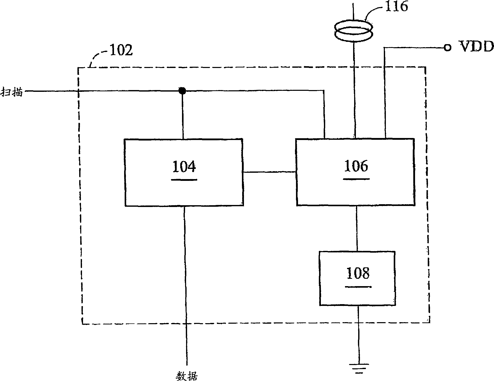
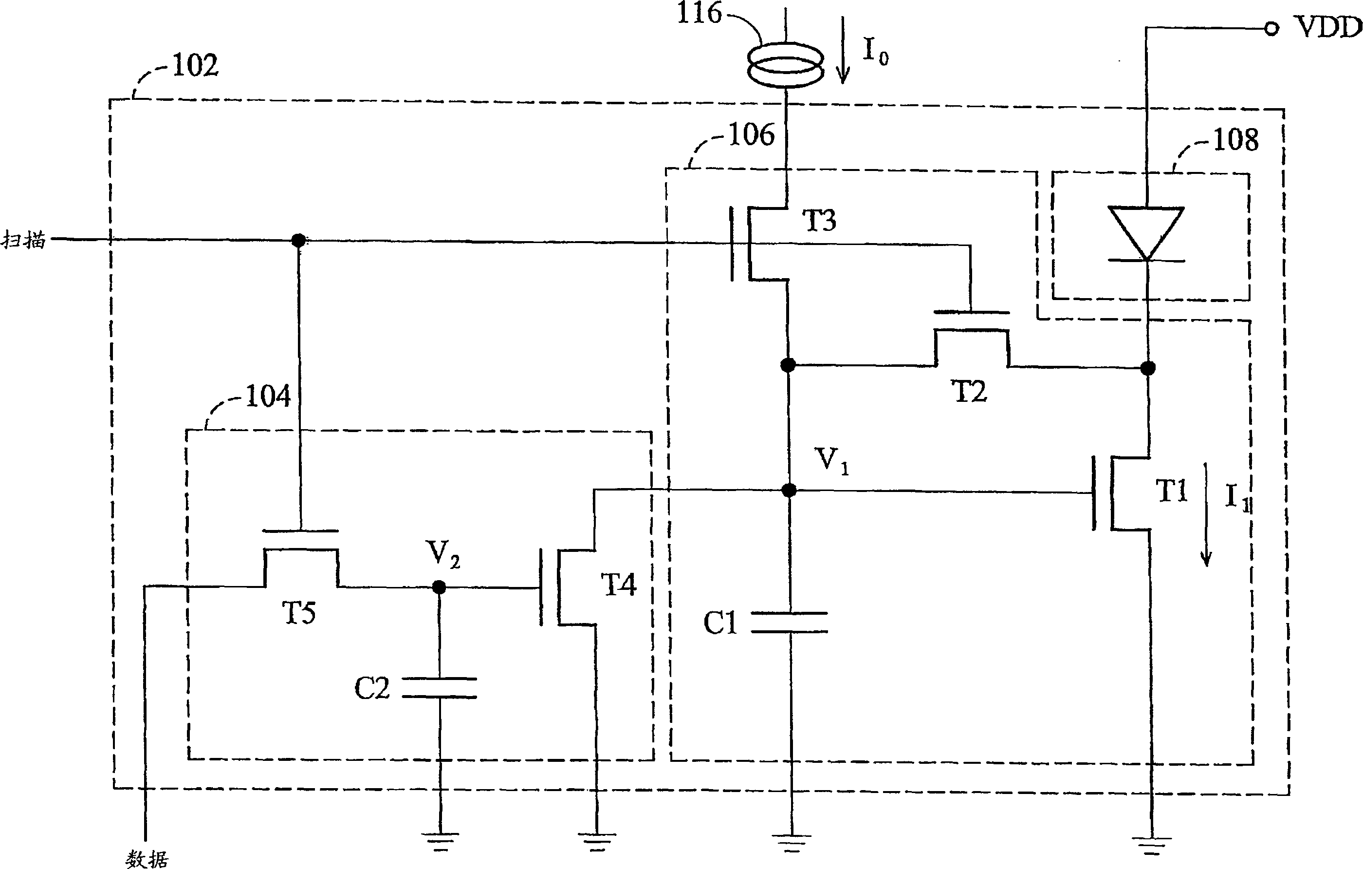
[0017] figure 1 It is a structural diagram of a pixel driving circuit according to Embodiment 1 of the present invention. A pixel circuit 102 mainly includes a discharge circuit 104 , a driving pump 106 and a light emitting diode 108 . The discharge circuit 104 is coupled to a scan signal SCAN and a data voltage DATA. The driving pump 106 is coupled to the discharge circuit 104 , the scan signal SCAN, and a current source 116 . The LED 108 is coupled to the driving pump 106 . The pixel circuit 102 starts to receive the data voltage DATA from the discharge circuit 104 ...


PUM


Abstract

This invention relates to an organic electroluminescence display and especially to a source electroluminescence display picture element drive circuit and method, which comprises the following steps: to charge one gray voltage with a fixed current into a saturation value to drive one light diode to emit; to write one data signal in form of voltage to control the charging speed of gray voltage to change the light diode time display and brightness to control the gray effect.

Description

technical field [0001] The present invention relates to an organic electroluminescence display, in particular to a pixel driving circuit and method for an active electroluminescence display. Background technique [0002] Organic electroluminescent displays typically use active organic electroluminescent diodes (AMOLEDs). There are two types of AMOLED driving methods: voltage writing and current writing. Voltage writing drive uses the thin film transistor (TFT) fabricated on the glass substrate to convert the written data voltage into a grayscale current to drive the AMOLED to emit desired brightness. However, due to the influence of manufacturing errors and temperature, the threshold voltages of TFTs are not consistent. Therefore, it is easy to cause image unevenness. As for the current writing drive, the written data current is recorded by TFT, so that the AMOLED can emit the desired brightness during the display cycle. However, current-driven integrated circuits have b...

Claims


Application Information

Patent Timeline
Patent Type & Authority Applications(China)
IPC IPC(8): G09G3/20G09G3/3233H05B44/00
Inventor 施立伟
Owner AU OPTRONICS CORP
Learn More