

Linkage sliding door
A linkage, door panel technology, applied in the direction of the arrangement of the wing leaf, the fastening device of the wing leaf, the fastening device of the building, etc., can solve the problems such as the inability to add parts, the time-consuming and laborious processing of the door panel, and the narrow utilization range, and achieve a quiet The effect of opening and closing, strengthening the connection force, and easy assembly
- Summary
- Abstract
- Description
- Claims
- Application Information
AI Technical Summary
Problems solved by technology
Method used
Image

Examples
Embodiment Construction
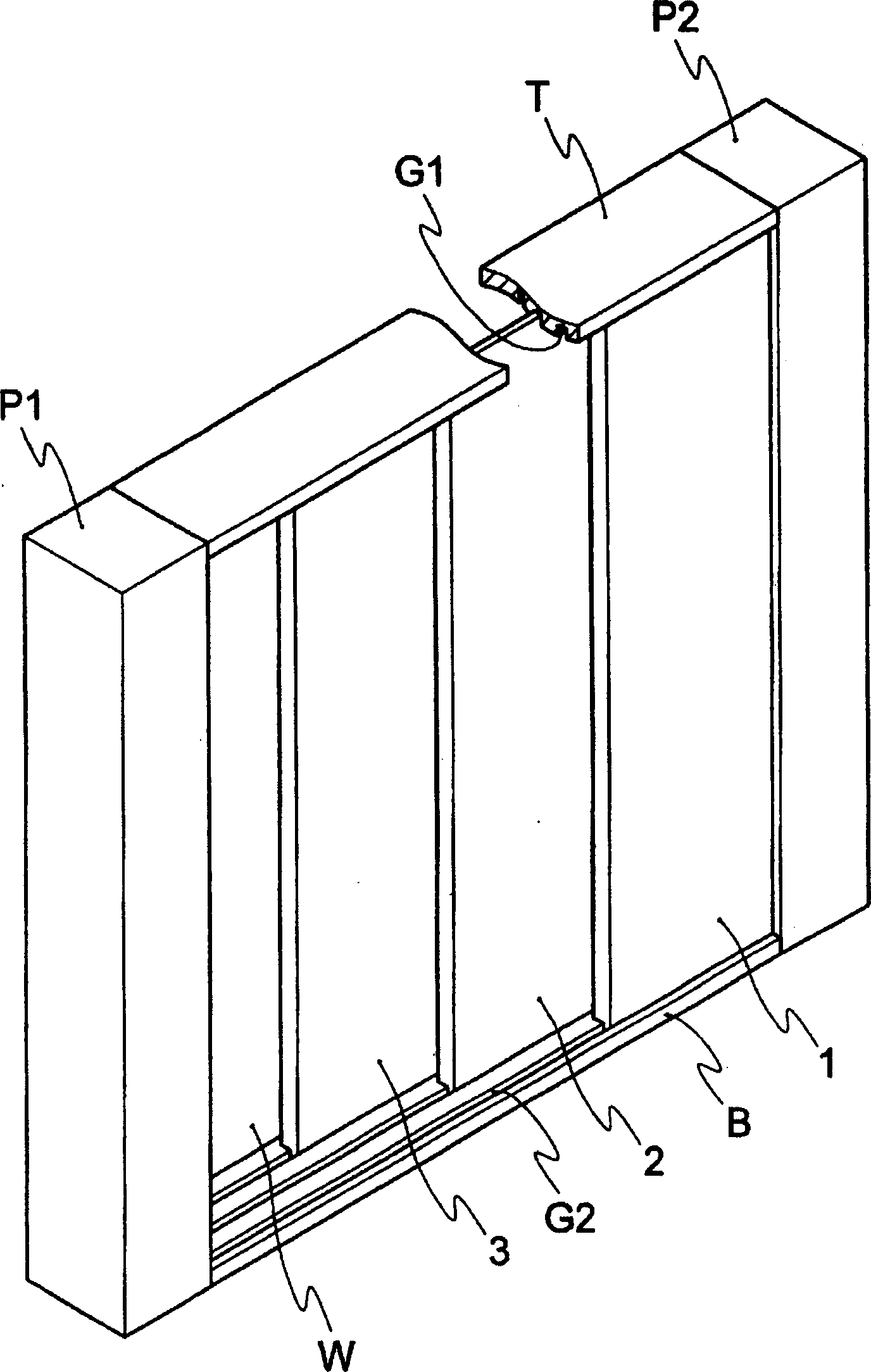
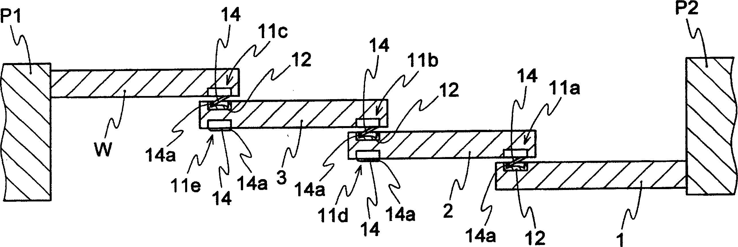
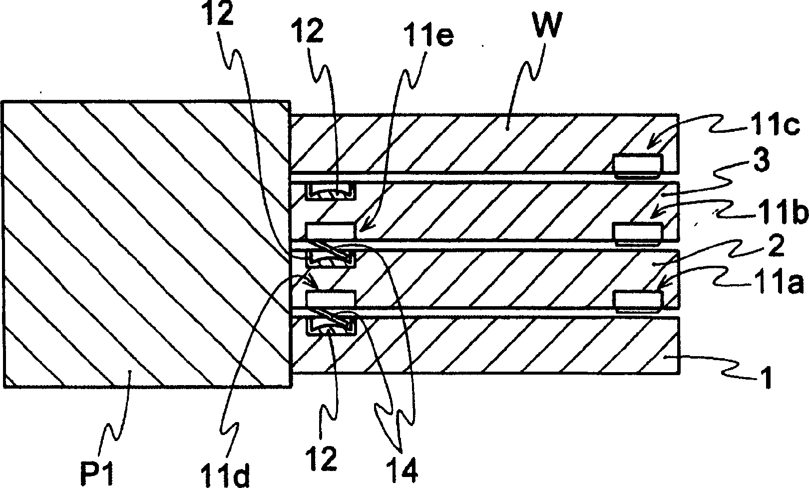
[0046] Next, the interlocking sliding door of the present invention will be described in detail with reference to the accompanying drawings. figure 1 It is a perspective explanatory view showing one embodiment of the interlocking sliding door of the present invention, figure 2 is to briefly show figure 1 The horizontal cross-sectional view of the arrangement of the protruding part and the receiving part of the fully closed state of the interlocking sliding door, image 3 is to briefly show that the figure 1 The horizontal cross-sectional view of the state where the interlocking sliding doors are fully opened (hereinafter also referred to as "full open"), Figure 4 yes figure 1 An enlarged perspective view of the door panel of Figure 5 yes Figure 4 The plan view of the protrusion, Figure 6 yes Figure 5 The VI-VI line profile, Figure 7 It is a partially cutaway front view of a movable tongue with a cushioning material as another embodiment of the present invention, ...
PUM
 Abstract
Description
Claims
Application Information