
Metallic beverage can end with improved chuck wall and countersink

A chuck, end wall technology applied in the field of metal beverage can end closures

Inactive Publication Date: 2005-07-13
BALL CORP +1
View PDF4 Cites 4 Cited by
  • Summary
  • Abstract
  • Description
  • Claims
  • Application Information

AI Technical Summary

Problems solved by technology

The beverage can ends described in the '634 patent do not use the standard double seam process well known in the industry

Method used


Image

  • Metallic beverage can end with improved chuck wall and countersink
  • Metallic beverage can end with improved chuck wall and countersink
  • Metallic beverage can end with improved chuck wall and countersink

Examples


Embodiment Construction

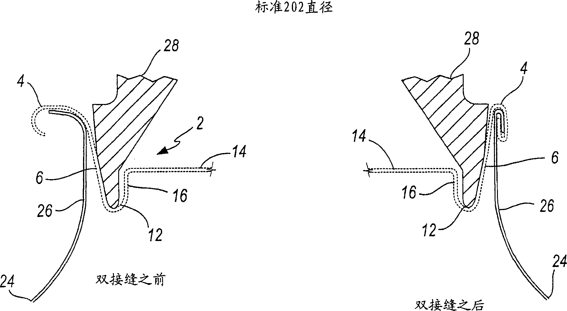
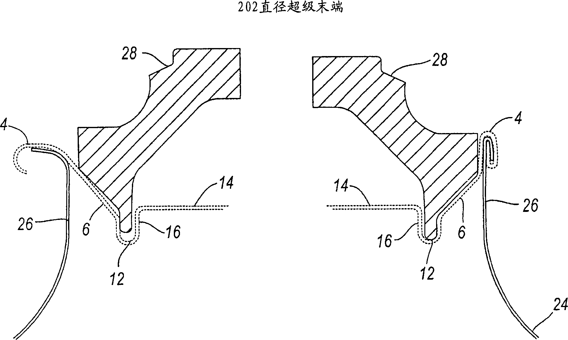
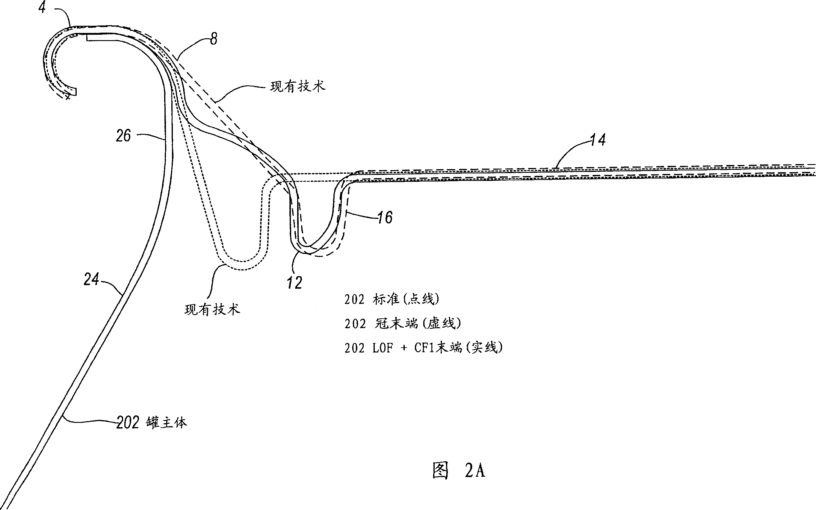
[0040] Referring now to FIGS. 1-7B , there are provided cross-sectional front views of prior art beverage can ends ( FIGS. 1-2A ) and various embodiments of the present invention ( FIGS. 3-7B ). More particularly, the metal beverage can 2 described herein generally consists of an annular end wall 4 , a chuck wall 6 , a countersink 12 , a center panel 14 , and an inner panel wall 16 interconnecting the center panel 14 to the countersink 12 . The chuck wall 6 may additionally include an upper chuck wall 8 and a lower chuck wall 10, which in some embodiments may have a first radius of curvature Rc1 and a second radius of curvature Rc2, respectively. In some embodiments, the inner panel wall 16 may additionally include an inner panel wall upper end 18 and an inner panel wall lower end 20 . Furthermore, the top of the annular end wall 4 is defined by what is typically called a crown 22 in beverage can art.

[0041] Here the chuck wall angle θ 1 is defined as the angle that the ch...


PUM

PropertyMeasurementUnit
thicknessaaaaaaaaaa
radiusaaaaaaaaaa
radiusaaaaaaaaaa

Abstract

The beverage can end (2) has a chuck wall (6), an inner panel (16) and a center panel (14). The radius of curvature of the concave bow on the chuck wall (6) is between about 0.015 and 0.080 inches.

Description

technical field [0001] The present invention relates generally to containers and container end closures, and more particularly to metal beverage can end closures adapted for interconnection with beverage can bodies. Background technique [0002] Containers, and especially metal beverage containers, are typically manufactured by interconnecting a beverage can end closure with the main body of the beverage container. In some applications, the end closure may be interconnected with both the top and bottom sides of the tank body. More often, however, the beverage can end closure is only interconnected at the top end of the beverage can body which is drawn and thinned from a flat sheet of blank material such as aluminum. Due to the potentially high internal pressure generated by carbonated beverages, both the beverage can body and the beverage can end closure are typically required to be able to support internal pressures in excess of 90 psi without severe and permanent deformat...

Claims


Application Information

Patent Timeline
Patent Type & Authority Applications(China)
IPC IPC(8): B65D8/04B21D51/32B21D51/38B21D51/44B65D6/28B65D6/34B65D8/12B65D8/20B65D51/26
CPCB21D51/32B21D51/38B21D51/44B65D7/36B65D2517/0062
Inventor 图安·A·古延杰斯·N·巴瑟斯特詹姆斯·A·里德克里斯托弗·G·尼纳
Owner BALL CORP
Learn More